DCS DCS-VH-36HS Manuale d'uso e d'installazione - Pagina 3
Sfoglia online o scarica il pdf Manuale d'uso e d'installazione per Cappa di ventilazione DCS DCS-VH-36HS. DCS DCS-VH-36HS 18. The professional vent hoods
Anche per DCS DCS-VH-36HS: Manuale d'uso e d'installazione (18 pagine)
INTRODUCTION:
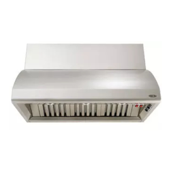
The Dynamic Cooking Systems Vent Hood Models have been designed with the ultimate in household
convenience in mind. Features include High Capacity,Variable Speed Blower, Commercial Style
dishwasher-safe filters, Easy-to-Clean inside liner, and Illuminating Halogen Lighting, all packaged in a
stylish, welded-seam exterior. Before proceeding with installation, please read this installation guide and
observe all safety precautions and warnings.
NOTE: Installation of this DCS Vent Hood must comply with all local codes.
IMPORTANT - Save these instructions for the Local Electrical Inspector's use.
INSTALLER- Leave these instructions with the unit for the owner.
SAFETY PRACTICES & PRECAUTIONS
...............................................................................3
..............................................................................................4
..................................................................................................................4
.................................................................................................................5
VENT HOOD INSTALLATION (WITH SOFFIT)
.........................................................6-7
VENT HOOD INSTALLATION (WITHOUT SOFFIT)
.................................................8
...............................................................................................9
DUCT INFORMATION
....................................................................................................................10
DCS VH SERIES SPECIFICATIONS
.........................................................................................11
........................................................................................................12
............................................................................................................................................13
WIRING DIAGRAM
......................................................................................................................14-15
2