AGS Parksafe Control Panel Manuale di installazione, funzionamento e manutenzione - Pagina 7
Sfoglia online o scarica il pdf Manuale di installazione, funzionamento e manutenzione per Controllore AGS Parksafe Control Panel. AGS Parksafe Control Panel 20. Ventilation control panel
Anche per AGS Parksafe Control Panel: Manuale di installazione e funzionamento (16 pagine), Manuale di installazione e funzionamento (16 pagine), Installazione Funzionamento e manutenzione (16 pagine)

Installation, Operation & Maintenance
6.
DETECTOR CHAIN.
24Vdc power and Modbus data connections to ParkSafe detectors.
Up to sixteen (16) ParkSafe detectors wire in series (daisy chain) up to approx. 500 yards per cable run from
the controller depending on chain configuration and wire type/condition.
7.
SHEILD.
For Modbus communication, a shielded and twisted pair cable is used. The shielding can be of two types:
braided [mesh of thin conducting wires] or foil (consisting of a thin sheet of metal covering the twisted wires).
To ground detectors the shield connects to the dedicated [Shield] terminals.
8.
SOUNDER/ STROBE.
This relay output (24vdc) is for external sounder alarms/ strobe lighting and will activate on alarm.
9.
24VDC
.
This is a permanent 24Vdc power output for external auxiliary devices. Max output: 200mA.
10. 0-10V OUTPUT.
This output signal sends either zero or 2V under normal operating conditions – selectable in the settings menu.
5V signal when [OUTPUT 1] relay switches. 10V signal when [OUTPUT 2] relay switches.
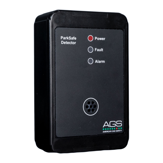
Wiring AGS ParkSafe Detector(s)
If you are encountering noise or irregular problems with a Modbus link, the problem is likely related to grounding, incorrect
shielding or wiring mains power next to Modbus wiring.
Reversing the [D+] and [D-] connections of any device can lead to the whole system to stop working owing to reverse polarity
found on the terminals.
Detectors should be grounded to limit the effects of R/F & EMC interference by connecting shield wires to shield terminals!
Ensure the [120-ohm chain termination resistor] switch on at each end of a cable run to limit noise!
Detectors connect to either [IN] or [OUT] terminal sets!
Consider the 24vdc power voltage drop due to cable resistance when connecting multiple detectors over long distances!
Rev: 20
ParkSafe Controller
7
