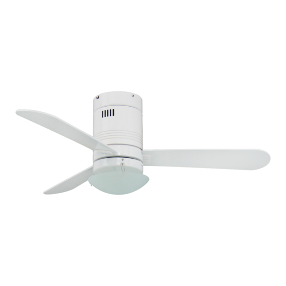
aireRyder FN44417 Manuale di istruzioni per l'installazione e l'uso - Pagina 3
Sfoglia online o scarica il pdf Manuale di istruzioni per l'installazione e l'uso per Ventilatore aireRyder FN44417. aireRyder FN44417 16.

1. Pass the supply wires through
the hole in the mounting bracket.
Secure the mounting bracket to a
ceiling joist or other structural
ceiling element with two screws,
spring washers and flat washers.
Ensure that the support for the
mounting bracket is capable of
safely holding the moving weight
of the fan.
Blue
Brown
Green/Yellow
From House
Terminal block on
Mounting bracket
4. Make wire connections. Follow diagram above and make sure that all exposed wires are tighten by
screw on terminal block.
Note: Wires from house may vary in color and may not included ground wire (green). After wiring is
completed, gently push wires into junction box with terminal block upward.
5-1. After the splicing has been
made, gently place the receiver
into the canopy and secure it in
place using double-sided adhesive
tapes which pre-adhered on the
back of the receiver.
5-2. Take off side screws (one of
each across) on mounting bracket
first, then loosen the other two.
8. Install a proper lamp to the
socket (E27, B Type, max. 60W,
not included).
2. Lift the fan assembly and hand
onto the hook on mounting
bracket. This will permit you to
make the electrical connections
without having to hold the fan up
as well.
Blue
Brown
Green/Yellow
From mounting bracket
6-1. Push up the canopy until the
two screws on mounting bracket
are engaged with L type slot
holes on canopy.
6-2. Rotate the canopy slightly
until the two screw heads are in
the L type slot holes.
6-3. Tighten 4 screws firmly.
9. Install the glass shade onto
the fan light housing using 3
spring clips.
3. There is a frequency-setter
respectively in the transmitter
and receiver. This "DIP Switch" is
a 4 key unit. All keys were set
at "ON" position in the beginning.
Set the keys to a different code.
Make sure the same numbered
keys are switched "ON" for both
DIP Switches. Take note that the
"ON" position may have different
orientation in each.
Blue
Blue (Motor-N)
Brown
Brown (Motor-L)
Orange
Orange(For light kit)
7. Attach blade to blade holder
with blade screw & paper washer
provided in hardware bag. Make
sure that all screws are firmly
tightened.
From Fan
3
