Gamber Johnson Recon CF31 Military Manuale di istruzioni per l'installazione - Pagina 7
Sfoglia online o scarica il pdf Manuale di istruzioni per l'installazione per Docking station Gamber Johnson Recon CF31 Military. Gamber Johnson Recon CF31 Military 10. Military docking station
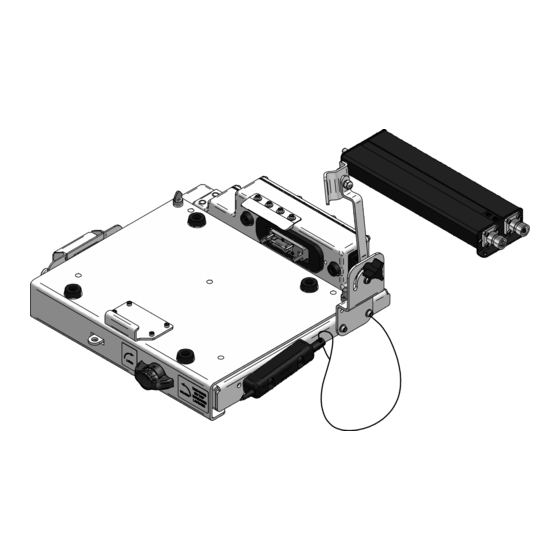
Connector Data cables are not supplied with the docking station
POWER SUPPLY CONNECTORS
15Vdc OUTPUT POWER TO
DOCK
AMPHENOL CONNECTOR
JD38999/20FA35SN
J6 PIN # J6 SIGNAL
1
PWR_OUT
2
GND
3
GND
4
GND
5
PWR_OUT
6
PWR_OUT
J1 = INPUT POWER
AMPHENOL CONNECTOR
#91-569781-35G
J1 PIN #
1
2
3
4
5
6
18 - 32Vdc INPUT POWER FROM
VEHICLE
AMPHENOL CONNECTOR
JD38999/20FA35PN
J5 PIN # J5 SIGNAL
1
PWR_IN
2
GND
3
GND
4
GND
5
PWR_IN
6
PWR_IN
J1 SIGNAL
PWR_IN
GND
GND
GND
PWR_IN
PWR_IN
NOTES:
1. It is recommended to install a
in-line fuse connected as close to the battery
or power source as possible.
2. The estimated power draw on the 28Vdc
vehicle supply is 3 Amps.
3. MIL STD 461F was achieved by using
completely shielded cables. Cables
containing USB signals must not exceed 5
meters in length.
32V - 10Amp
J2 = DATA CABLE
AMPHENOL CONNECTOR
#91-569783-35H
(1)VIDEO, (1)AUDIO,
(1)USB ETHERNET
J2 PIN #
J2 SIGNAL
1
VSYNC
2
HSYNC
3
DDC2BD
4
NC
5
SYNC_GND
6
+5V_VIDEO
7
CRTB_GND
8
CRTG_GND
9
CRTR_GND
10
GND
11
NC
12
CRTB
13
CRTG
14
CRTR
15
USB_RXP
16
USB_TXN
17
USB_TXP
18
HP_R
19
HP_L
20
AGND
21
DDC2BC
22
USB_RXN