Jafar 4493SA Manuale operativo - Pagina 12
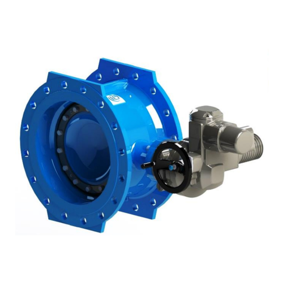
Sfoglia online o scarica il pdf Manuale operativo per Unità di controllo Jafar 4493SA. Jafar 4493SA 14. Double eccentric flanged butterfly valve
As standard, the manufacturer offers fittings for dry chambers and directly for installation in the ground. The IP68
protection class (part turn gearbox) does not define the exact operating ranges of the products, such as: immersion
depth (a value is specified; at least 1m), the pressure value acting on the product and the valve immersion time.
The fittings may be used in chambers (tanks) only after prior agreement between the customer and Fabryka
Armatur Jafar. - special realization. As stated in point 2, the control is carried out by a T- key, stands or an
electromechanical actuators including fixed casing Product Number 9025. When mounted in the ground, the
manufacturer recommends the use of a street box Product Number 9501 mounted on a base plate Product Number
9521 or an equivalent product ensuring rigid foundation of the box. More information on the use of street boxes
for underground installations is described in the "Operating Manual for PE-HD street boxes Product Number
95xx".
In case of installing butterfly valve housings in chambers, it is forbidden to transfer the weight of the housing
to the valve gearbox. It is absolutely necessary to use stabilizers or other relieving elements, which are
mounted to the walls of chambers. Exceeding the limit moments given in Table 4 in point 6 may result in
mechanical damage to the JFR GRAY part-turn gearbox.
Note that the completed installation must not expose the valve to bending or tensile stress from loading with the
unsupported pipeline sections. Install the product properly aligned with the piping centreline and with proper
parallelism and flatness of the mating connection flanges, with prevention of hydraulic shock, and with due
compensation of the pipeline dimensional changes from temperature and pressure. A valve assembled and adjusted
by the manufacturer is ready for installation in the system. Any dismantling of the valve components (e.g. the
shaft, the closure panel, or sleeves) may result in loss of seal.
The requirements for correct quality of the mating flanges have to be satisfied, that is flatness and parallelism,
during the installation process. During the installation process, do not leave any installation tools, bolts, nuts, or
welding wire inside of the piping or they can stop in the sealing seat of the butterfly valve or on the flap (disc).
This may lead to damage of the seat during closing of the valve and loss of seal across the valve. The outer diameter
of the flat seals installed the pipeline and butterfly valve flange faces must be equal to or higher than the outer
diameter of the face. It must never less than the outer diameter of the face. Place the flat seals aligned with the
centreline of the flap sealing ring (the outer diameter of the flat seal must be equal to the nominal diameter of the
piping). The tightness is ensured by an elastomeric seal in the disc groove, attached with a clamping ring to the
valve flap.
The manufacturing tolerance of the valves and their components are large enough to ensure full interchangeability.
The user carries out the installation of the valve in the pipeline on his or her own accord.
Use proper intrinsically safe tools and avoid all actions which may lead to fire during all repair and maintenance
work.
Before attempting to install the valve, check the technical and commercial documents delivered with the product
to verify that your media and pipeline operating parameters comply with the manufacturer's declaration.
If the butterfly valve is installed at the end of piping, mount a steel or cast-iron stub pipe on the free end of the
butterfly valve to guard the disc during opening.
Any change in the operating conditions must be consulted with the valve manufacturer beforehand.
Before attempting to assemble the valve, remove the main bore plugs, check the inner surfaces of the valve and
thoroughly flush with water, if necessary. When installing butterfly valves between the pipeline flanges, first
remove all transport preservation from the surfaces, thoroughly clean the flange faces, install the seals, and screw
down with screws long enough to tighten the adjacent flanges of the pipeline together. The valve and piping flange
holes must be aligned.
Having completed the installation, perform a pressure test at a maximum test pressure equal to 1.5 times
the nominal pressure in the fully open or 1.1 times the nominal pressure in fully closed position.
Caution! If the product has mechanical damage, do not install it in the pipeline.
The pipe inner diameter shall be equal to the nominal diameter (DN) of the valve plus the tolerance for the
deviations provided for by the foundry industry for the given pipe I.D.
If the valve is installed with an operator or an operator and gearbox unit, check the electrical wiring and fire-proof
protection features (also during coupling and adjustment of the operator) for conformity with the respective
operating manuals from the operator drive unit manufacturer.
OPERATING MANUAL
07-2022
12/14