Majestic fireplaces Al Fresco ODGSR42A Manuale d'installazione e d'uso per il proprietario della casa - Pagina 6
Sfoglia online o scarica il pdf Manuale d'installazione e d'uso per il proprietario della casa per Camino da esterno Majestic fireplaces Al Fresco ODGSR42A. Majestic fireplaces Al Fresco ODGSR42A 20. Outdoor gas fireplace

ODGSR Series Outdoor Gas Fireplace
Black
Mantel
Surround
Leg
Face
CFM164
Side of
CFM164a
Combustion Chamber
Mantel Leg Chart
06/22/01 sta
Ref.
Mantel
Leg Depth
F
14" (356 mm)
CFM170
G
12" (305 mm)
DV Builder Front
View
H
10" (254 mm)
I
8"
(203 mm)
J
1¹⁄₂" (38 mm)
Fig. 3b Combustible mantel leg minimum installation.
Moisture Resistance
This outdoor fireplace will shed moderate amounts of
water, but is not waterproof. Water and condensing wa-
ter vapor may enter the chase under certain conditions.
The fireplace will not perform as an exterior wall. Mois-
ture penetration must be considered for construction
that places the fireplace in structure walls or on mois-
ture sensitive surfaces.
When installed on exterior walls: CFM Corporation
recommends the fireplace chase be constructed outside
the structure's weather envelope. Where the platform
meets the wall, use a flashing detail similar to that
required for attached decks. Chase platforms, including
hearths should slope away from the structure at 1/4 in
per foot. The fireplace can be shimmed level.
When installed on surfaces where water may collect or
cause damage: CFM Corporation recommends a slope
of 1/8 in to 1/4 in per foot towards the drain port sug-
gested. The fireplace can be shimmed level.
6
J
I
H
G
F
K
L
M
N
O
CFM170
Ref.
Mantel Leg From
of Comb. Opening
K
14"
(356 mm)
L
12"
(305 mm)
M
10"
(254 mm)
N
8"
(203 mm)
O
1¹⁄₂"
(38 mm)
Hearths should slope away from the front of the fire-
place and chase at 1/8 in to 1/4 in per foot. Metal safety
strips must be on top of any combustible hearth materi-
als used for moisture management.
Framing and Finishing
Check appliance to make sure it is levelled
and properly positioned.
The appliance should only be mounted on the following
surfaces:
•
A flat combustible (burnable) surface.
•
A raised wooden platform.
•
A concrete block or other solid object placed
beneath each of the four corners of the appliance.
To mount the appliance:
1. Choose unit location.
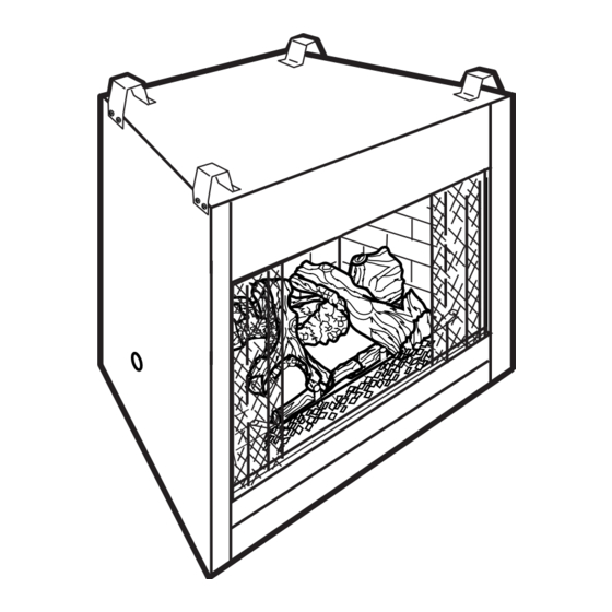
2. Four (4) nailing flanges are supplied with the fire-
place (found on the fireplace hearth). To level the
box and secure it firmly in place, remove the nailing
flanges from the hearth and install at the sides of the
fireplace as shown in Figure 4.
Fig. 4 Adjustable drywall strip (nailing flange).
Finishing
CAUTION: All joints between the finished
wall and the appliance surround (top and
sides) may be sealed only with non-com-
bustible material. Only noncombustible
material can be applied as facing to the ap-
pliance surround (the black painted face).
Finish the wall with the material of your choice. Refer to
Figures 3a and 3b for specific clearances when install-
ing a combustible mantel or other combustible projec-
tion.
Nail Top
Standoffs
Nail Side-
Nailing
Flanges
FP549
FP549
9/29/97
BR/BC
20007114
