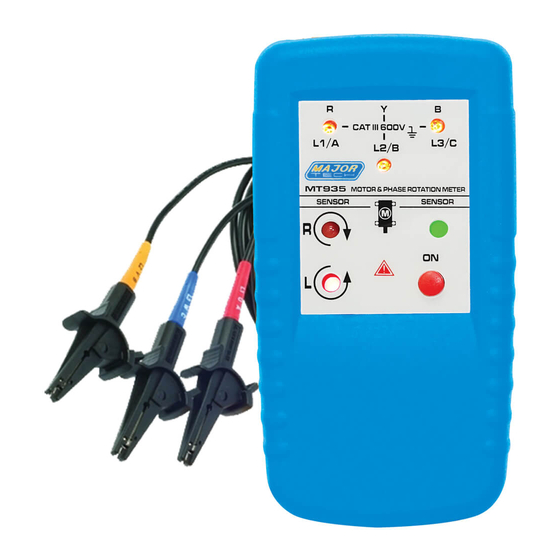
Major tech MT935 Manuale di istruzioni - Pagina 4
Sfoglia online o scarica il pdf Manuale di istruzioni per Strumenti di misura Major tech MT935. Major tech MT935 8. Phase rotation meter with rotary field direction
Anche per Major tech MT935: Manuale di istruzioni (8 pagine)

See table 2 for the minimum motor diameter and number of pole pair to
obtain a reliable test result.
Table 2. Reliable Motor Test Requirements
Number of
pole pair
1
2
3
4
5
6
8
10
12
16
Determine the Motor Connection
1.
Connect on end of the test leads to the motor and phase rotation meter.
Make sure the L1, L2 and L3 test leads are connected to the
corresponding jack.
2.
Connect the croc clamps to the other end of the test leads.
3.
Connect the croc clamps to the motor connections, L1 to U, L2 to V, L3
to W.
4.
Press the ON/OFF button. The green ON indicator shows that the
instrument is ready for testing.
5.
Turn the motor shaft half a revolution towards the right.
Note:
The bottom of the motor and phase rotation indicator should be oriented
towards the drive shaft. See the orientation symbol on the motor and phase
rotation meter. Either the clockwise or counter clockwise rotary indicator
illuminates showing the type of rotary field direction present.
Magnetic Field Detection
To detect a magnetic field, place the motor and phase rotation meter to a
solenoid valve. A magnetic field is present if either the clockwise or the
counter clockwise rotary indicator illuminates.
Note:
The motor and phase rotation meter contains alkaline batteries. Do not
dispose of these batteries with other solid waste. Used batteries should be
disposed of by a qualified recycler or hazardous materials handler.
Rotary Number Of Rotary Field
(1/min) at Frequency (Hz)
⅔
16
50
1000
3000
500
1500
333
1000
250
750
200
600
167
500
125
375
100
300
83
250
62
188
Angel Between
poles
60
3600
60
1800
30
1200
20
900
15
720
12
600
10
450
7.5
360
6
300
5
225
3.75
Min. Ø of
Motorcase
cm
5.3
10.7
16.0
21.4
26.7
32.1
42.8
53.5
64.2
85.6
