Centurion POLOphone Manuale di installazione - Pagina 4
Sfoglia online o scarica il pdf Manuale di installazione per Sistema interfonico Centurion POLOphone. Centurion POLOphone 17. Entry panel
Anche per Centurion POLOphone: Manuale di installazione (16 pagine), Manuale di installazione (17 pagine), Procedura di messa in servizio (4 pagine)

Specifications
Operating Voltage
Quiescent
Current draw
Maximum
Speech volume
Wiring / Cabling
Ring tone
Call confirmation at entry panel
Wiring / Cabling distance
Gate / Door release
Handset auxiliary contact
Handset indicator lens
Entry panel illumination
Operating temperature
Humidity
IP rating
Surge protection
* NB: If 12V DC gate motor supply dips when motor starts up and the intercom is being used
at the same time, the speech quality might be affected.
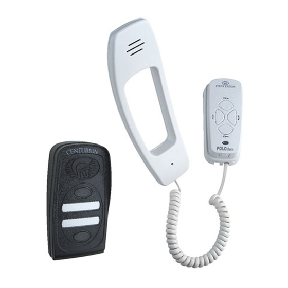
The POLOphone system is supplied as separate components:
Component 1-Entry panel (with two call buttons) consisting of:
A
B
Page 4 - POLOphone Intercom
12 to 14V DC (14V DC if powering handset)
Supplied from gate motor DC supply* or
separate 14V DC supply
150mA (+/- 60mA for a 1:1 system)
200mA
Adjustable at each entry panel and handset
Two polarized wires for speech, call and
gate/door lock release
Electronic while button is depressed, with
separate tones when calling from each entry
panel in a system or between groups of handsets
Yes
Max 150m - Refer to cable thickness on page 7
2A 12V AC/DC Potential-free normally-open
contact at entry panel. Door lock requires
separate power supply wired in series with contact
Potential-free normally-open contact. Requires
separate wiring to two wire bus. Contact rating:
2A @ 12V DC/AC
LED terminals on PCB 470Ohm in-line resistor.
Requires separate wiring to 2 wire bus.
Call buttons and labels backlit
-20°C to +50°C
0 to 90% non condensing
IP56
Yes
2 X Mounting screws
2 X Rawlplugs
1 X Mounting screw sealing washer
1 X Cover retaining screw
2 X Call button labels
