Major tech MT560 Manuale di istruzioni - Pagina 7
Sfoglia online o scarica il pdf Manuale di istruzioni per Apparecchiature di prova Major tech MT560. Major tech MT560 12. Digital insulation tester

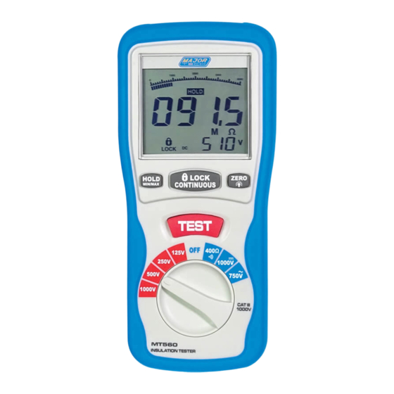
4. PARTS & CONTROLS
1. Digital Display
2. Data Hold Button; MAX/MIN
3. Lock Button
4. Backlight Button; ZERO
5. Test Button
6. Rotary Function switch
7. VΩ Jack
8. COM input jack
9. Pothook
10. Battery Cover
4.1. How to connect test leads.
On MΩ Range, and 400Ω/BZ, ACV, DCV, Connect the red test lead into the
"VΩ" terminal and the black lead into the "COM" terminal.
4.2. Battery Check-UP & Replacement
a) As battery power is not sufficient. LCD will display
. Replacement of
6 pcs new batteries, type 1.5V size "AA" is required.
b) Place back the battery cover and four the screws.
4.3. Test leads check
Set the range select switch to the 400Ω range. With the tip and alligator
clip of the test leads connected. The indicator should read 00.0Ω. When
the leads are not connected the display will read infinity indicated by "OL".
This will ensure that test lead are under working condition.
4.4. Rotary Switch positions
Turn the Tester on by selecting any measurement
Lift < 1000V, 500V, 250V, 125V (4000MΩ)
, 1000VDC, 750VAC > Right
OFF 400Ω/
4.5. Buttons and a display Indicators
a) Button
HOLD/MAX.MIN: Press the "HOLD" button to ensure the current values
are held on the primary display. Once held on the display, hold down the
button for 2 seconds for the display to read the "MAX" value. Click again to
view the "MIN" value. Hold down the button for 2 seconds to exit.
LOCK: In the insulation resistance testing function, press the
"LOCK" button, and then push down the "TEST" key, it will allow hands
free operation to inject the high-voltage and enter the insulation resistance
testing status. Press the "TEST" button once more, it will shut off the high-
voltage and exit from the insulation resistance testing status.
7
