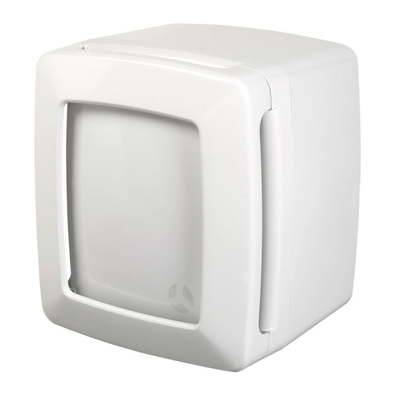
Airflow LOOVENT eco HT Manuale operativo - Pagina 3
Sfoglia online o scarica il pdf Manuale operativo per Ventilatore Airflow LOOVENT eco HT. Airflow LOOVENT eco HT 8. Loovent eco series centrifugal fans

2. Mechanical Installation
The LOOVENT eco fan range can be surface mounted or recessed in a wall or ceiling in a vertical
or horizontal position (not suitable for window installation).
Dimensions
Figure 2
Front Cover Removal
The front cover of the fan has a snap type fitting.
To remove, apply finger pressure to the two
semi-circular buttons at the edge of the cover
(Figure 5). This releases the cover from the body
of the fan allowing it to be pivoted. To remove the
cover completely, pivot it to 90° and lift away
(Figure 6).To refit, reverse the above procedure .
Fan Module Removal
Remove the accessories (fixing kit, adjustor tool,
anti-backdraught flap (or cone in the dMEV version))
from the body of the fan. The fan module is released
by undoing the two retaining screws alongside the fan
housing (Figure 7). Lift the left side of the module as viewed
slightly and slide to the right to release from the two lugs in the
base (Figure 7).
Recessing in the Wall
The fan can be mounted "landscape", with the release
buttons facing downwards or "portrait" with the buttons on
the right hand edge. The fan requires a 110mm diameter
hole through the external wall lined with a 100mm internal
diameter duct kit (refer to Page 8 for accessories). The internal
wall requires a recess of 195 x 175 x 80mm deep. Important:
refer to the enclosed mounting template in the Box for location
of recess and fixing screws relative to the exhaust ducting.
Surface Mounting on the Wall
The fan can be mounted "landscape", with the release
buttons facing downwards or "portrait" with the buttons on
the right hand edge. The fan requires a 110mm diameter
hole through the wall lined with a 100 mm internal diameter
duct kit (refer to Page 8 for accessories). Important: refer to
the enclosed mounting template the box for location of fixing
screws.
Figure 3
Figure 5
Page 3 of 8
Figure 4
Figure 6
Figure 7
Figure 8
Figure 9
Screw
Lugs
Screw
