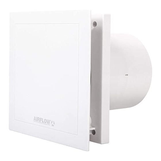
Airflow QT 120T Istruzioni per l'installazione e il funzionamento - Pagina 4
Sfoglia online o scarica il pdf Istruzioni per l'installazione e il funzionamento per Ventilatore Airflow QT 120T. Airflow QT 120T 4. Quietair 100/120mm axial fan
Anche per Airflow QT 120T: Manuale di installazione e istruzioni per l'uso (7 pagine)

Installation and Operation Instructions
4.0
Electrical connection
CH PTER 4
ELECTRIC L
CONNECTION
ll work must be carried out with the equipment fully isolated from the power supply. The electrical connection
W RNING
is to be carried out in accordance with the relevant wiring diagram and are only to be done by a certified
electrician. The fan may not be operated with transformer controllers.
All relevant safety regulation, national standards and norms are to be adhered to.
4.1
Electronic control board
The electronic control board allows the operation with 2 speeds (75/90 m
The control board is fitted into a splash-proof casing.
NOTE
EMV regulation
Important indication for the electromagnetic compatibility
Interference resistance according to DIN EN 55014-2 depending upon impulse form and energy rate of 1000 V to
4000 V. With operation with fluorescent tubes, switch power supplies, electronically regulated halogen bulbs etc. these
values can be exceeded.
In this case additional suppression shielding activities are necessary (L -, C or RC elements, protection diodes,
resistors).
CH PTER 5
5.0
Cleaning and maintenance
- Before cleaning, ensure that the fan is isolated from the power supply.
CLE NING ND
- Prevent unintentional restart !
M INTEN NCE
- Clean device only with a damp cloth.
- The device is maintenance-free.
5.1
Dismantling of fascia
Procedure:
1. Isolate the device from the power supply and prevent unintentional restart!
2. Remove the fascia (1) by using the correct tool (e.g. screw driver) and applying light pressure on the spring catches
left and right of the fascia (Fig.10).
3. Unfasten the screws of the control board cover (2) (Fig.11).
CH PTER 6
6.0
Troubleshooting
- If the thermal protection trips this could be the result of dirt build-up, a hard running impeller and/or bearings.
TROUBLESHOOTING
Too high winding temperature through insufficient motor cooling, or too high air flow temperature could be the cause
of disturbance.
- Abnormal noises can mean worn out bearings.
- Vibrations can originate from an unbalanced or dirty impeller or due to the installation.
- Extreme performance reduction can occur if the fan must work against too high resistance of the ventilation system
or if there is a lack of sufficient supply air (causing also higher sound level).
3
hr) for QT100B & (150/170m
4
Installation and Operation Instructions
Wiring diagram overview
Quiet ir 100B - 75 (90)m
3
/hr
Quiet ir 120B - 150(170)m
3
/hr
3
hr) for QT120B.
Footnotes:
a) During parallel connection of the terminal 1-2 an inverse
voltage rests respectively against the other not switched terminal.
Connect room lighting only via two-pole switch.
Functional description:
The fan QT100B is equipped with two speeds (75/90 m³/h) and
QT120B (150/170 m³/h) and operated with a two speed switch
(optional).
1
2
N
L
1 2
a)
a)
L
L
L
N
N
L
1
2
5
5
SS-930
I
0
SS-921
