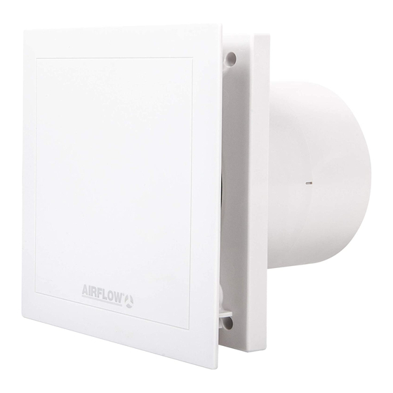
Airflow QuietAir QT 100T Manuale di installazione e istruzioni per l'uso - Pagina 8
Sfoglia online o scarica il pdf Manuale di installazione e istruzioni per l'uso per Ventilatore Airflow QuietAir QT 100T. Airflow QuietAir QT 100T 8. 100mm axial fan
Anche per Airflow QuietAir QT 100T: Istruzioni per l'installazione e il funzionamento (5 pagine)

Model_QT_100T 27/05/2009 16:51 Page 4
Installation and Operation Instructions
Wiring diagram overview
WARNING
Electrical connection:
- Terminal N / L:
The supply voltage of 230 V is connected permanently to
terminal N/L
- Terminal 1:
The time functions are activated via terminal 1.
The following functions are implemented:
1. Start delay (without or 2 minutes.)
After switching on terminal 1, the fan starts first after the adjusted
delayed time. Thus a room can be entered for a short time (via
two-pole switch) e.g. during combined on/off switching with the
light without the fan being started for operation. Factory setting
approx. 2 minutes.
DIP-switch S1-1 wiring diagram SS-920: No.1: off = deactiva-
ted, on = 2 minutes.
2. Operation with push-button switch
During start delay the fan can be switched on via terminal 1 with a
push-button switch at deactivated start delay (sampling pulse min.
0,5 sec.).
3. Run on time (6 min., 12 min., 15 min., 21 min.)
After switching off terminal 1, the fan keeps running and switches
off after the adjusted time automatically. Factory setting approx.
15 min.
DIP-switch S1-2+3 (see wiring diagram SS-920)
4. Interval operation - Auto Refresh
Interval operation (4hrs., 8 hrs., 12 hrs., 24 hrs.)
The fan can be put in adjustable time intervals into operation auto-
matically. After the adjusted run on time the fan switches off auto-
matically. The interval time starts after the last switch off process
on terminal 1 (time input), also with manual operation in the mean-
time (terminal 2). The manual operation does not have influence on
the interval operation. The turn-on time in the interval operation
corresponds to the adjusted run on time. Factory setting approx. 4
hrs.
DIP-switch S1-4+5 (see wiring diagram SS-920)
The interval operation can be deactivated with DIP switch S1-6,
set to "on".
5. Changing the factory setting
DIP-switch (see wiring diagram SS-920). Isolate the unit from the
mains electric supply !
- Terminal 2:
The continuous operation is activated via terminal 2 (see wiring
diagram SS-917). With activated time function, the manual stage
(terminal 2) is inactive.
Room lighting
In connection with the room lighting (terminal 1 or 2), a two-pole
switch must be used.
Connection client
a) time function
b) manual on
Internal functional principle / Jumper position
time function/- input
manual input
Adjustment of DIP-switchs
Important: Wiring in parallel
Wiring in parallel of several fans is not permitted.
- Jumper
Depending on the jumper setting, the fan runs with 75 or 90 m³/h.
Jumper 1 (see wiring diagram SS-931)
Position A – Factory setting
Kl. 1 = 75 m³/h, activation via time function
Kl.2 = 90 m³/h, manual on
Position B
Kl.1 = 90 m³/h, activation via time function
Kl.2 = 75 m³/h, manual on
Operation test – Test mode:
When applying the supply voltage the fan is in the test mode for 1 minute.
(Requirement: Factory setting of DIP-switch, see wiring diagram SS-920)
In this case the delayed start and the overrun function is deactivated within the first
minute, or for a switching cycle.
5
5
SS-931
SS-920
15 min
21 min
21 std
