Gantner 631325 Manuale - Pagina 3
Sfoglia online o scarica il pdf Manuale per Serrature Gantner 631325. Gantner 631325 7. Battery powered mifare and iso 15693 lock
Installation Instructions
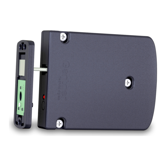
The GAT ECO.Side Lock 7000 is mounted on the inside of the locker wall
using 3 screws. The bolt set including door shackle is attached to the inner
side of the locker door. For non-metallic doors, only a drill hole through the
locker door is required for the status LED. For metallic doors, a cut-out
must be made in the locker door to accommodate the bolt set and label
carrier. For glass doors, the metal support is attached to the locker door
using adhesive.
Note: The GAT ECO.Side Lock 7000 needs min. 10 mm clearance from
the bottom or top of the locker to allow the hole marking gauge to
be used for installation.
Door status contact
The GAT ECO.Side Lock 7000 has a contact that is activated or deactivated
by the door contact (5) on the bolt set when the locker door is closed or
opened respectively. This function determines the open/close state of the
door. It is important that this contact remains clean and undamaged to
ensure the correct functionality of the GAT ECO.Side Lock 7000.
Mounting on Non-Metallic Doors
6
2
7
5
6
8 mm
17 mm
(0.31´´)
(0.67´´)
Installation requirements for GAT ECO.Side Lock 7000 and bolt set
Please pay particular attention to the following points:
- When the locker door is pressed shut, ensure there is no gap between
the bolt set (2) and the front of the GAT ECO.Side Lock 7000. Ideally
the bolt set should touch the front of the lock.
- The front side of the bolt set and the GAT ECO.Side Lock 7000 must be
aligned parallel to each other.
Installation procedure
Note: Before installing all locks in a new locker system, a test installation
of at least one lock and a final function check must be performed.
Only once the functional testing is successfully completed may the
remaining locks be installed in the same way.
1. Drill three holes (3) for the GAT ECO.Side Lock 7000 into the locker
wall.
2. Insert the batteries into the GAT ECO.Side Lock 7000 (see page 7).
3. Mount the GAT ECO.Side Lock 7000 with three screws (3) on the
inside locker wall.
Attention: Use the correct screws according to the type of locker
material, max. Ø 4 mm (0.16´´). The maximum allowed
tightening torque of the screws is 2 Nm (1.47 lb-ft).
www.gantner.com
1
3
3
3
74 mm (2.91´´)
Door width
The minimum allowed door width (measured from the door shackle to the
hinge) is 230 mm (9.05´´). If the door is narrower than this measurement,
the door shackle will hit the locker when the door is being closed.
Locker door
15 mm (0.59´´)
1
6
3
2
3
7
3
6
14.6 mm (0.57´´)
17.6 mm (0.69´´)
4. Drill three mounting holes (6) for the GAT NET.Lock Bolt Set 7100.
5. Drill a hole for the status LED in the locker door (7). The recommended
hole diameter is 10 mm.
6. Mount the bolt set onto the locker door using three screws.
Attention: Use the correct screws according to the type of locker
material, max. Ø 4 mm (0.16´´). The maximum allowed
tightening torque of the screws is 2 Nm (1.47 lb-ft).
7.
A label (GANTNER standard design or custom design) can be
attached to the locker front. If a custom label design is used, ensure
that a transparent field for the LED light is included in the label design.
8. Test the locker door to confirm that it can close easily and the door
shackle inserts correctly into the GAT ECO.Side Lock 7000.
Valid from June 10th, 2015 • Technical data subject to modification without notice!
DB_GAT-ECOSide-Lock7000--EN_11.indd • Part No. 642832
Centre of hinge rotation
min. 230 mm (9.05´´)
1. GAT ECO.Side Lock 7000
2. GAT NET.Lock Bolt Set 7100
3. Mounting screws for the
GAT ECO.Side Lock 7000
5. Door contact
6. Mounting screws for bolt set
7. LED (hole in locker door)
3