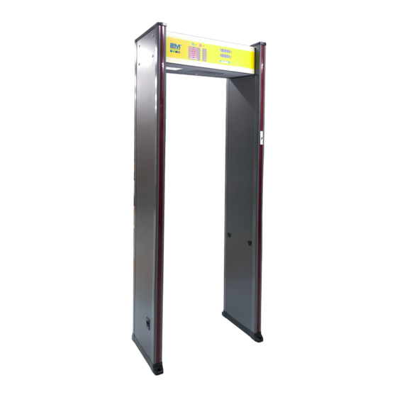
2M Technology 2MTHWT-HMD Manuale d'uso - Pagina 15
Sfoglia online o scarica il pdf Manuale d'uso per Metal Detector 2M Technology 2MTHWT-HMD. 2M Technology 2MTHWT-HMD 20. Walkthrough metal detector
Anche per 2M Technology 2MTHWT-HMD: Manuale d'uso (8 pagine), Manuale rapido (12 pagine)

as well as impacting the door plate are not allowed.
4. For the WTMD inspection, the person shall be inspected after the last one passes the warning line without triggering
the alarm. If an alarm is triggered, the person shall be inspected after the alarm tone stops.
5. A person passing through the Walk-through Metal Detector (WTMD) triggers the alarm means that metal articles are
carried. The metal article location can be found according to the indication of the LED light bar (The bought "Hand met-
al detector" produced by our company can used together).
6. The person to be inspected shall not wear jewelries or clothes, caps and footwear with metallics for fear of affecting
normal inspection of metal articles.
COMMON PROBLEM HANDLING
I.
Infrared sensor counting failure
1. Check both ends of the sensor leads in the main case for being correctly connected.
2. If both ends of the sensor leads are connected correctly, check the emission voltage of the infrared modules for being
in good condition. Resistor R5 and R286 are emission ends. The voltage R5 / R286 and U2 / U36 connecting ends is
approx. 2.5V. D2 and D13 are reception ends. When the infrared is not blocked, the voltage of the 3rd pin of D2 and
Dl 3 is close to OV. When the infrared is blocked, the voltage of the 3rd is higher than 3V. If the voltage of the infrared
module emission and reception ends is normal, check IC U21 of the main controller.
3. If one or a pair of the infrared module emission and reception ends does not work, the infrared tube shall be checked
for being burnt or bad connection or the system for bad wiring.
II. False alarm
1. If frequent false alarm appear, check the installation conditions of the Walk-through Metal Detector (WTMD) for meeting
the "Installation conditions".
2. If the installation meets the "Installation conditions", check the right / left door plates for being installed backwards.
3. If the door plates are installed correctly, try to decrease the sensitivity of all zones and check the false alarm for being
handled.
4. If this problem is still not handled through decreasing sensitivity, check the voltage for being normal. Normal working
voltage shall be 110 - 240V. False alarms might be caused if the voltage is lower than 11OV (handling method: Try to
buy an adjustable booster or a back-up UPS power supply).
5. If the working voltage is kept within the normal range, check the oscillation frequency for being normal. Stagger the
interference by changing the frequency and the perform further tests.
III. Startup failure
1. If a startup failure appears, check the voltage for being kept within a normal range. If the supply voltage is lower than
90V, the machine will not be started up (Try to buy an adjustable booster).
2. If the voltage is kept within a normal range, check the input end of the switching supply. If no voltage is found, check the
fuse for being burnt out. If the voltage is normal, check the output end voltage of the switching supply for being 12V. If
the voltage is 12V, check the voltage values of the motherboard and MCU for being 5V and 3.6V respectively.
IV. Alarm failure
1. If an alarm failure occurs, check the alarming mode firstly. If the alarming mode is "With infrared", the alarm is only
available with infrared counting; If the alarming mode is "Without infrared", check the oscillation signal for normal out-
put.
www.2MTechnology.net
2M Technolgy User Manual
15
