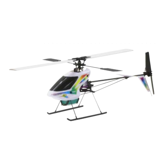
Century Helicopter Products Hummingbird Elite Series FP Manuale di istruzioni - Pagina 4
Sfoglia online o scarica il pdf Manuale di istruzioni per Giocattolo Century Helicopter Products Hummingbird Elite Series FP. Century Helicopter Products Hummingbird Elite Series FP 12. Elite series helicopter

Section 2
Section 2
Section 2
Section 2
Section 2
TESTING AND PREPARATION OF RADIO EQUIPMENT
PLEASE DON'T SKIP THIS SECTION
Before modifying or installing any radio gear,
please take a few minutes to test everything
as shown. Time spent becoming familiar with
the equipment and testing all the components
can prevent difficulty.
1. Install the crystals into the transmitter and
receiver. Be certain that the channel
frequency matches.
2. Note that all electronics plug into the receiver with the wires as pictured (orange wire faces
receiver label). Follow the diagram for each electronic connection. Once the electronics
system is connected and the transmitter is turned on, follow this step-by-step process to
check your equipment.
STEP-BY-STEP COMPONENT TEST
IMPORTANT:
!
1. Turn on the transmitter - Does
All connections shown in
the green LED turn on?
this manual work for
Futaba, Hitec & Century
2. Plug the "Bird Seed" battery
radio systems. If you
have any other radio
into your mixer board and wait for
system please consult
the flashing LEDs on the mixer
your radio instructions
board and the gyro to stop
for channel numbering.
flashing.
(some equipment may
differ in appearance.)
ELECTRONIC CONNECTION OVERVIEW
This diagram represents the
overall connections for wiring
the Hummingbird Elite
correctly. This diagram
includes the separate
connections pictured above.
IMPORTANT:
!
If you have the FP and
Century Lightning 4
channel radio please
refer to the wiring
diagram provided with
the radio system.
MODIFYING THE SERVOS FOR INSTALLATION
1. A long half arm may have to be created by
cutting a full or cross arm.
2. After testing the radio equipment the servos
will be in their center position. Remove the servo
retaining screw and servo wheel. Replace the
wheel with one of the long half arms. See section
3 for the final positions for your version.
3. Some servo arms require widening the hole in the arm in order for them to accept the
Hummingbird's pushrods using a #55 drill bit [1.34mm or 0.052"].
4
Connection And Diagnostics F
Connection And Diagnostics F
Connection And Diagnostics For The
Connection And Diagnostics F
Connection And Diagnostics F
Electronic Components
Electronic Components
Electronic Components
Electronic Components
Electronic Components
1
3. Move the right hand stick on
the transmitter left to right -
does the aileron servo move?
4. Move the right hand stick
forward and back - does the
elevator servo move?
Century Micro
Receiver
CN2032
1 2 3 4 5 6
Channels
Note:
Aileron Servo (ch.1)
Signal (s)
Positive (+)
CN2023
Negative (-)
(move left & right)
Elevator Servo (ch.2)
CN2023
Tail Motor
(move front & back)
(ch.4) CNE019
(turn left & right)
1
Throttle Connection
Back of Hummingboard
2
Servo Connections
6 5 4 3 2 1
Channels
Rudder & Gyro Connections
1 2 3 4 5 6
Channels
Motor Connections
The mixer speed controller controls the amount of power
transfered to the main and tail motors in proportion.
Collective
Pitch Servo
(ch.6 CP only)
CN2023
(blade pitch)
Micro Gyro
CN2022E
There are 2 wires coming from the upper
left corner of the board. The top wire is
marked rudder on the front of the board.
This wire goes into the gyro. Bottom wire
Gyro: signal faces
goes to the receiver for the throttle.
signal connection
Main Motor
(ch.3) CNE056
(go up & down)
or The
or The
or The
or The
Ch#1
Ch#6
Ch#2
Aileron
Pitch (CP)
Elevator
The gyro helps
the helicopter
maintain rudder
heading. Without
the gyro the
helicopter might
spin out of
control.
Front of
Hummingboard
Bird Seed Battery
7 Cell 8.4V
CNE050
Bird Seed Battery
8 Cell 9.6V
CNE050A (optional)
Mixer and speed control Board
CNE052
Connect the tail motor and main motor
connectors to the board, note that the
two red wires are beside each other when
connected to the board as marked by
positive and negative indicators.
2
3
