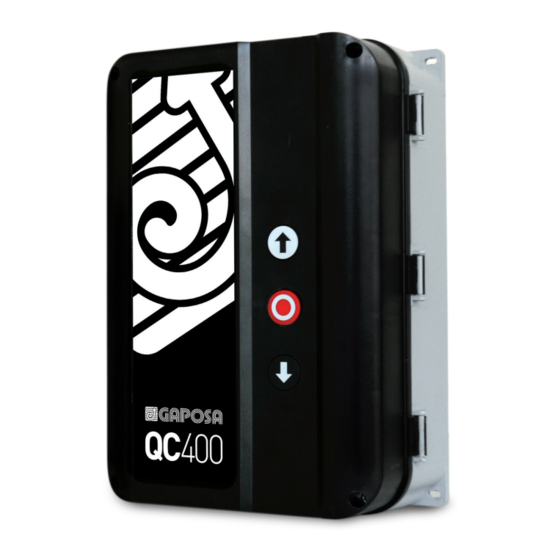
GAPOSA QC400 Manuale - Pagina 11
Sfoglia online o scarica il pdf Manuale per Motore GAPOSA QC400. GAPOSA QC400 16. Automatic control unit for three/single-phase motors with digital or mechanical limits

5.1 PROGRAMMING WITH ELECTRONIC LIMIT SWITCH
ATTENTION: to let the safeties work, these must be connected before starting the control unit setup.
Setting process
Turn OFF the power and connect the encoder and all safety equipment.
1
The controller memorises the encoder type by power-up.
Set DIP10 in ON position and turn the power ON. Activate setting by pressing OPEN + STOP for about 10 sec until the
red LED FAIL (PCB) starts with 2 short flashes
2
ATTENTION: Switching DIP10 to ON position and back to OFF will reset to mechanical standard with ONLY PNE edge
type.
First press the CLOSE button to the desired down limit position.
Note: if door is moving in the wrong direction the 2 phases on the mains connection must be interchanged.
3
(Alternatively choose the special phases interchange function by pressing OPEN + STOP for 20 sec. - Yellow LED SPE-
ED/SER confirming with 1 sec.)
4
Press STOP to set the down limit position. Yellow LED SPEED/SER confirming with 1 sec
Press OPEN to the desired UP limit position.
5
By open position you can adjust the UP limit position finely by running OPEN and CLOSE, but first operation must be in
OPEN direction for minimum 2 sec.
Press STOP button to save the UP limit position, encoder direction, edge type and photo
6
Yellow LED SPEED/SER confirming with 1 sec
Limits are now adjusted and edge type and photo circuit are set.
7
Check that the safety edge and photo functions are working as expected.
5.2 LED GUIDANCE
Yellow LED CONF./SER. (PCB)
Service needed (open
Fixed light
counts reached)
Confirming setting process
1 sec. flash
Red LED FAIL (PCB)
If Photo or Edge is activated
Fixed light
when CLOSE pushbutton is
activated
No answer from encoder.
1 short flashes
Check RS485
1 long flash
Auto close setting active
Limits, edge and photo not
2 short flashes
learned
Force control (speed) not
2 long flashes
learned
3 long flashes
Door stopped by force control
Calculation failure (e.g. both
4 short flashes
limits the same)
4 long flashes
Door stopped by runtime
Door stopped by force control
5 long flashes
wear
6 long flashes
Tacho failure – pulses missing
Encoder position out of learned
7 short flashes
area. (Reset by power up or
resetting)
Kostal encoder – Power
8 short flashes
failure.
Fail state PNE edge monito-
Continues long
ring. Check impuls by floor
flashes
missing.
Yellow LED STOP (PCB)
Stop activated or both limits
Fixed light
are active
1 long flash
Safety chain activated
2 long flashes
Photo – safety test failed.
3 long flashes
Safety edge – safety test failed.
4 long flashes
Stop circuit – safety test failed.
5 long flashes
Safety chain – safety test failed
EEPROM failure. Elec. Counter
6 long flashes
or position counter by force
control
EEPROM failure. Powerup
7 long flashes
failure
8 long flashes
Welded contactor fail
9 long flashes
Internal watchdog timeout.
10 long flashes Main processor crystal fail
Green LED POWER (PCB)
The controller is powed
Fixed light
Red LED CIRCUIT ERROR (PCB)
PCB circuit error fail
Fixed light
11
