Jamara 061260 Istruzioni - Pagina 4
Sfoglia online o scarica il pdf Istruzioni per Trasmettitore Jamara 061260. Jamara 061260 16. Throttle left, throttle right
Anche per Jamara 061260: Istruzioni (16 pagine), Istruzioni (16 pagine), Istruzioni (16 pagine), Istruzioni (16 pagine), Istruzioni (16 pagine)

DE
2.
Cómo activar
1. Poner todo junto.
2. Encienda el transmisor.
3. Conectar la batería al receptor.
4. El LED rojo se enciende permanentemente el receptor, lo que significa que la existencia de
una señal real.
5. El sistema se activa y se puede utilizar.
3.
Apagar secuencia
1. Desconecte la batería del receptor
2. Apague el transmisor
1
2
3
4
5
6
7
8
9
10
11
22
23
4
Encender la emisora
Power ON
GB
2.
Power on
1. Connect all parts.
2. Switch on the transmitter.
3. Connect the receiver battery.
4. The receiver red LED indicator is solid indicating the presence of a correct signal.
5. Use the radio system.
Desconectar la emisora
Power OFF
3.
Shut down
1. Disconnect the receiver battery.
2. Switch off the transmitter.
12
13
14
15
16
17
18
19
20
21
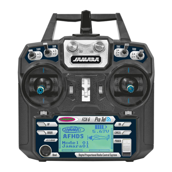
DE - Descripción gas izquierda
1
Antena 2,4 GHz
2
Botón VRB (Programable)
3
Interruptor B (Programable)
4
Interruptor A (Programable)
5
Modo 2 = Mando de paso/cola
Modo 4 = Mando de paso/alabeo
6
Trim de paso
7
Modo 2 = Trim de cola
Modo 4 = Trim de alabeo
8
Botón arriba
9
Botón abajo
10 LCD
11 Botón de encendido
12 Botón VAA (Programable)
13 Interruptor C (Programable)
14 Interruptor D (Programable)
15 Ojal para correa
16 Modo 2 = Mando alabeo/cabeceo
Modo 4 = Mando cabeceo/cola
17 Trim de cabeceo
18 Modo 2 = Trim de alabeo
Modo 4 = Trim de cola
19 Botón confi rmación (Enter)
20 Exit/Atrás botón
21 Interruptor On/Off
22 Canal que desee introducir el cable simulador
23 Compartimento de la batería
GB - Definition of key funktions throttle left
1
2,4 GHz Antenna
2
Rotary poteniometer VRB (free programmable)
3
Switch B (free programmable)
4
Switch A (free programmable)
5
Mode 2 = Throttle/Rudder stick
Mode 4 = Throttle/Aileron stick
6
Throttle Trim
7
Mode 2 = Rudder Trim
Mode 4 = Aileron Trim
8
Key up
9
Key down
10 LCD Display
11 Bonding button
12 Rotary poteniometer VAA (free programmable)
13 Switch C (free programmable)
14 Switch D (free programmable)
15 Hook
16 Mode 2 = Aileron/Elevator stick
Mode 4 = Elevator/Rudder stick
17 Elevator Trim
18 Mode 2 = Aileron Trim
Mode 4 = Rudder Trim
19 Enter button
20 Exit / Back button
21 Power switch
22 Simulator connecter
23 Battery box
