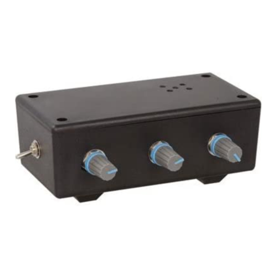
Jameco Electronics FORREST M. MIMS III: ATARI PUNK CONSOLE KIT Istruzioni per il montaggio
Sfoglia online o scarica il pdf Istruzioni per il montaggio per Sintetizzatore Jameco Electronics FORREST M. MIMS III: ATARI PUNK CONSOLE KIT. Jameco Electronics FORREST M. MIMS III: ATARI PUNK CONSOLE KIT 3.

FORREST M. MIMS III: ATARI PUNK CONSOLE KIT | JAMECO PART NO. 2155487
VISIT WWW.JAMECO.COM/PUNK FOR COMPLETE KIT BUILD
Experience Level: Beginner-Intermediate | Time Required: 30 minutes - 1 hour
The Atari Punk Console has become the popular name for a simple circuit that Forrest first described
as a "Sound Synthesizer" in Engineer's Notebook: Integrated Circuit Applications (1980) and then a
"Stepped Tone Generator" in Engineer's Mini-Notebook: 555 Circuits (1984).
How It Works
The circuit consists of a 556 dual-timer IC (equivalent to a pair of 555 timers) and half a dozen other
parts. In operation, the first timer is connected as an audio frequency oscillator and the second as a
monostable multivibrator. The oscillator drives the monostable, which emits square output pulses
with a duration controlled by R3. You have to hear the end result to fully appreciate the stepped
tones that are generated as R1 and/or R3 are adjusted.
R1 controls the frequency of the audio oscillator. R2 controls the output pulse duration of the
monostable multivibrator. R4 is an optional volume control that can be deleted by connecting the
speaker directly to C3.
Assembly Instructions
Place and solder each component corresponding to their respective spots on the PCB. Here are
some tips on how to distinguish which parts are which:
1) The capacitance values for C1 and C2 can be measured using a multimeter. Otherwise,
looking at the capacitor, C1 is marked with "103", where C2 is marked with "0.1"
2) C3 is the electrolytic capacitor with the cylindrical shape. This capacitor is polarized so find
the negative side with the black stripe and place it accordingly on the board. (Figure 1)
