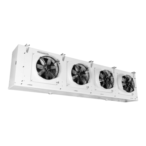
FRIMETAL GNHB Manuale di istruzioni - Pagina 14
Sfoglia online o scarica il pdf Manuale di istruzioni per Condizionatore d'aria FRIMETAL GNHB. FRIMETAL GNHB 20. Industrial evaporators

DESCONGELACIÓN POR AGUA
Este sistema de descongelación se ofrece como opción para
todas las gamas de evaporadores industriales aunque princi-
palmente para los modelos de tipo cúbico como los FR y GR.
Los elementos que incorpora un evaporador para este siste-
ma y su funcionamiento son los siguientes:
1 Unas "duchas" rectangulares (una por cada ventilador) en
aluminio con la base agujereada que se encargan de
repartir el agua del desescarche por la parte superior de la
batería. Para facilitar su limpieza y mantenimiento son
fácilmente desmontables.
2 Conexión rosca macho de latón para la entrada del agua
(uno por cada ducha) por la parte trasera del evaporador.
3 Bandeja recogegotas para reconducir hacia el desagüe el
agua salpicada de la batería y evitar que caiga a la cáma-
ra.
4 Conexión para la salida del agua en latón con rosca hem-
bra G 2-1/2".
En los catálogos de los FR, GR y GNH se dan las dimensio-
nes de las conexiones de plástico de las duchas y el caudal
de agua que cada modelo necesita. Este es un dato aproxi-
mado que hay que ajustar al instalar el aparato. Las duchas
llevan unos tubos rebosaderos que, cuando se llenan, des-
alojan el agua sobrante por ambos extremos. Hay que regu-
lar el caudal hasta dejarlo en un punto de equilibrio. Si es muy
bajo puede ser insuficiente para un óptimo desescarche y si
es muy alto el exceso de agua puede producir salpicaduras
que caigan a la cámara.
14
WATER DEFROSTING
This defrosting system is offered as an option for all ranges
of industrial evaporators though mainly for cubic shaped
units as the FR and GR.
The elements included for this system and their functioning
are as follows:
1 Some rectangular aluminium "showers" (one for each fan
motor) with the bottom holed to spread the defrosting
water all over the upper part of the coil. They are easily
removable to facilitate the cleaning and maintenance ser-
vice.
2 Brass male thread connection for the inlet water piping (one
for each shower) placed at the back of the evaporator.
3 A back tray to re-collect the water splashed from the coil
and to carry it back to the drain hole, preventing its falling
into the cool room floor.
4 Connection for the water outlet made of brass with female
thread G 2-1/2".
In the FR, GR and GNH catalogues the dimensions of the plas-
tic tube connections of the showers and the water flow that
each model needs are given. This is an approximate data that
is necessary to adjust when installing the unit. The showers
have some overflow holes (one at each end) that, in case of
excess of water feeding and shower fill-up, let the spare water
go through. It is necessary to regulate the water flow until a
balanced quantity is reached. If this flow is too low, it may not
be enough for an optimal defrosting and if it is too high, the
water excess can splash and fall into the cool room.
