Jandy Jandy Pro Series Manuale - Pagina 2

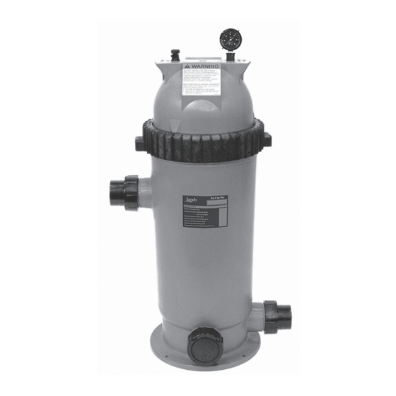
Sfoglia online o scarica il pdf Manuale per Filtro per piscina Jandy Jandy Pro Series. Jandy Jandy Pro Series 8. Single element cartridge pool & spa cs filters
Anche per Jandy Jandy Pro Series: Manuale d'uso (12 pagine), Manuale di installazione (16 pagine), Manuale di installazione e funzionamento (20 pagine), Manuale d'uso (20 pagine), Manuale di avvio rapido (2 pagine), Manuale di installazione e funzionamento (20 pagine), Istruzioni per l'installazione (2 pagine), Manuale di installazione e funzionamento (16 pagine), Manuale di installazione e funzionamento (16 pagine), Manuale di installazione e funzionamento (16 pagine)

Jandy Jandy Pro Series Manuale
Page 2
3. Installing Power Pack R-Kits
WARNING
Disconnect power to the system at the main circuit
breaker before performing this procedure to avoid
risk of electric shock which can result in property
damage, severe injury or death.
Control PCB Assembly
(R512300)
Power PCB
Assembly
(R512100)
Output Cable Assembly
(R512500)
Figure 1.
Power Pack R-Kits
A. Replacing the Power Pack Cover
Assembly, and the Control PCB
Assembly
Disassemble to the component that needs replacement.
1. Ensure that all power to the power pack and the
controller is disconnected/turned off at the circuit
breaker.
2. Detach the outer dress cover from the power pack
by pressing on each of the sides and lifting up
(see Figure 2).
Figure 2.
Power Pack Installed
Jandy
Pro Series AquaPure
®
Power Pack Cover Assembly
(R0512400)
Outer Dress Cover
To remove the outer
dress cover, press on the
sides and lift up.
|
Ei™ Series
Replacement Kit Instructions
®
3. Remove the screws attaching the cover to the back
plate and prop the cover up to expose the terminals.
Unplug the ribbon cable from the Power PCB
(see Figure 3).
Power PCB
Figure 3.
Unplug Ribbon Cable
4. Remove the power pack cover from the back plate.
Turn the cover over and remove the four (4) screws
attaching the Control PCB to the cover.
5. Attach the new Control PCB to the cover using the
four PCB mounting screws provided in the kit
(see Figure 4).
Figure 4.
Control PCB Installed
6. Plug the ribbon cable into the Power PCB.
7. Reattach the cover to the back plate using the four
(4) mounting screws.
8. Reattach the outer dress cover.
9. Reconnect the power.
Unplug the
Ribbon
Cable