Gardena 1254 Manuale dell'operatore - Pagina 8
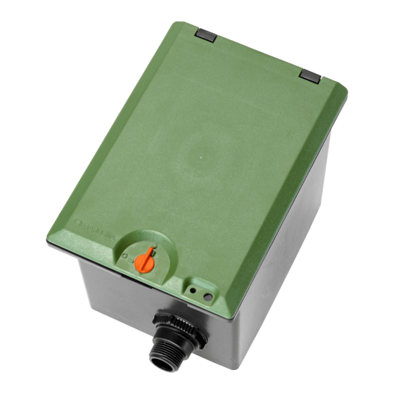
Sfoglia online o scarica il pdf Manuale dell'operatore per Attrezzature per prato e giardino Gardena 1254. Gardena 1254 11. Valve box
Anche per Gardena 1254: Manuale di istruzioni per l'uso (8 pagine), Manuale dell'operatore (8 pagine), Manuale di istruzioni per l'uso (9 pagine)
1. SAFETY
IMPORTANT!
Read the operator's manual carefully before use and keep for future
reference.
WINTER STORAGE!
Read the notes on safety in the Valve Box.
Before the frost period starts: see 3. STORAGE
To put into storage / Winter storage.
Please observe the notes on safety in the operating
instructions.
2. ASSEMBLY
A video on how
to assemble the
V3 Valve Box can
be found here:
Note: Assemble the screw connections for all parts by hand;
do not use tools.
(Fig. 1) Grease all O-rings and metal securing clips with accompany-
ing silicone grease.
(Fig. 2.1) The distributor (C) has three connections. Screw end
caps (D) onto the unused distributor inputs.
(Fig. 2.2 – 2.5) Insert the distributor and connections (G) and secure
with the nuts (E). Fit the drain cap (F).
(Fig. 3) Insert the long telescopic pipe (I) into the connection on the
outlet side (securing clip facing upwards).
(Fig. 4) Screw the short telescopic pipe (J) into the input side of the
valve. Arrows on valve show the direction of flow.
(Fig. 5.1) Insert the valve with the short telescopic pipe into the input
side of the box.
(Fig. 5.2) Screw the long telescopic pipe (I) into the outlet side of the
valve (I).
(Fig. 5.3 + 5.4) Press down the securing clips. If necessary, screw in
the telescopic pipes until such point as the clips move down without
much resistance.
(Fig. 6) Insert a short telescopic pipe (J) into the open distributor
outlet on any channels that are not needed.
(Fig. 7) Underlay the valve box with a pack of coarse gravel and set it
in place so that it is level with the turf.
V1: min. 20 x 30 x 10 cm; V3: min. 35 x 30 x 10 cm
(Fig. 8) If connecting a number of valve boxes, use suitable connec-
tors as per illustration.
Tip: When using more than one valve box, screw them
sidebyside onto a wooden board to secure them.
3. STORAGE
To put into storage / Winter Storage:
The following precautions must be taken – especially
before the frost period starts – to prevent damage to the
Irrigation Valves:
1. Close the water tap and disconnect the hose from the GARDENA
Water Connection Point Art. 2722.
2. If the watering system is directly connected to the water tap, turn off
the water supply and open the venting tap.
3. Set the selection lever (Fig. 12) a of all valves to the "ON" position.
4. Draining the Irrigation Valve / Valve Box.
There are various ways to drain the system:
• Drain the system by blowing out the water with compressed
air.
• Remove all the valves and store in a place protected from
frost.
10
A video on how
to install the
valves can be
found here:
DANGER!
This product makes an electromagnetic field while it operates. This field
may under some conditions interfere with active or passive medical
implants. To decrease the risk of conditions that can possibly injure or
kill, we recommend persons with medical implants to speak with their
physician and the medical implant manufacturer before you operate the
product.
DANGER!
Small parts can be easily swallowed. There is also a risk that the poly-
bag can suffocate toddlers. Keep toddlers away when you assemble the
product.
(Fig. 9) Insert the terminal strip (N) into the bracket.
(Fig. 10) Connection from 1 V3 Valve Box to 3 24V valves:
• For better mapping, label the valves using the yellow, numbered
stickers (1 – 15).
• Strip the individual cables of the connection cable (7 x 0.5 mm
Art. 1280) and connect with terminals 1, 2, 3 on the water control
and the V3 Valve Box. Connect another individual cable to the
terminal (C) on the water control and the V3 Valve Box.
• Connect a cable from each of the valves 1, 2 and 3 to terminals
1, 2 and 3 on the valve box. Connect the second cable of the valves
to the terminals (C) in the valve box.
Connecting a further V3 Valve Box with 3 valves:
• Connect the cable to terminals 4, 5, 6 on the water control and the
first V3 Valve Box.
• Connect a cable from each of valves 4, 5 and 6 to terminals
4, 5 and 6 on the second valve box. Connect the second cable of
valves 4, 5 and 6 to the terminals (C) in the second valve box.
• Use a short length of cable to connect terminals 4, 5, 6 and C on the
first valve box to terminals 4, 5, 6 and C on the second valve box.
(Fig. 11) Press the protective cap (O) over the terminal strip (N) and
secure using the two screws (M).
(Fig. 12) Setting the valve controls:
Fully automatic control:
• Set selection lever to "AUTO / OFF".
Program-controlled water flow to watering system as per program-
ming on water control.
An automatically opened valve cannot be manually closed on
the valve.
Manual control:
• Set selection lever to "ON".
Permanent water flow, independent of programming.
(Fig. 13) To protect against theft, the lid can be secured with a small
padlock or hasp (not included).
• With Valve Box V3, open the draining cap (F) and empty the
supply line. You can leave the Watering Valves in the Valve
Box provided that the lines leading from the Valve Box V3
are drained via a draining valve (e. g. in the GARDENA Popup
Sprinklers) that is installed lower than the Watering Valve.
5. Remove the battery from the Control Unit.
6. Lock the box lid (Fig. 13.3).
Disposal:
(in accordance with RL2012/19/EC)
The product must not be disposed of to normal household
waste. It must be disposed of in line with local environmental
regulations.
IMPORTANT! Dispose of the product through or via your
municipal recycling collection centre.
,
2