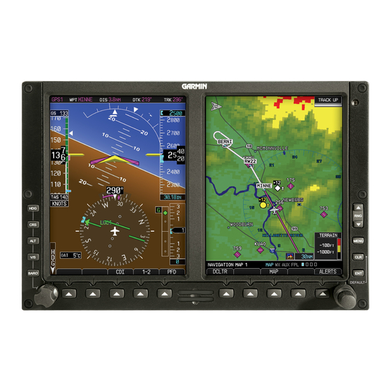
Garmin G500 Manuale di istruzioni - Pagina 9
Sfoglia online o scarica il pdf Manuale di istruzioni per Display avionico Garmin G500. Garmin G500 14. Primary flight and multifuction display system
Anche per Garmin G500: Riferimento rapido (2 pagine), Manuale (40 pagine)

2.5.11 TBM 700(850) RVSM Periodic Maintenance (G600 Only)
Maintain all RVSM equipment in accordance with the manufacturer's maintenance and performance
requirements. The encoding altimeter must be checked as specified in the Socata Maintenance Manual
section 05-10-01, ATA 34. The RVSM critical areas must be inspected as specified in Socata
Maintenance Manual section 05-10-01, ATA Chapter 53.
The air data systems must be checked within the preceding 24 months as specified in the Socata
Maintenance Manual section 34-11-00 except the altitude displays and Altitude Alerter must be tested in
accordance with the G500/G600 AML STC Installation Manual section P.3.2.1. Socata Maintenance
Manual test procedures may be adapted to complete all other air data system checks required in the
G500/G600 AML STC Installation Manual section 5.8.2.
The autopilot altitude hold performance must be tested within the preceding 24 months in accordance
with the G500/G600 AML STC Installation Manual section P.3.3.
2.6 Troubleshooting Information
If error indications are displayed on the GDU 620 display unit, and/or the optional Mid Continent
Instruments standby attitude indicator, consult the Troubleshooting section contained in the G500/G600
AML STC Installation Manual. The 'G500/G600 System Post-Installation Checkout Log' in the aircraft
permanent records includes the configuration information for the installation (see Section 5 in the
G500/G600 System AML STC Installation Manual for a sample Log).
2.7 Removal and Replacement Information
If any G500/G600 LRUs are removed and reinstalled, verify that the LRU unit power-up self-test
sequence is successfully completed and no failure messages are annunciated on the GDU 620 display.
See the unit replacement procedure in Section 3.5 of the G500/G600 AML STC Installation Manual.
Perform any additional procedures that are required for each LRU, as specified in the following
subsections. Any component installed under this STC must be replaced by a component of the same
model and part number or defined equivalent component.
If any work has been done on the aircraft that could affect the system wiring, antenna cable, or any
interconnected equipment, verify the G500/G600 system unit power-up self-test sequence is
successfully completed and no failure messages are annunciated on the GDU 620 display.
Refer to the G500/G600 AML STC Installation Manual (listed under reference documentation in Section
2.1 of this document) for particular LRU removal/installation procedures and special handling
precautions.
2.7.1
GAD 43e Adapter Replacement
If the GAD 43e is used with an analog navigation receiver, the GAD 43e calibration specified in 5.5.11.3
of the G500/G600 AML STC Installation Manual must be performed whenever the GAD 43e and/or the
analog navigation receiver is replaced.
2.7.2
TBM 700(850) RVSM Return to Service (G600 Only)
If the GDC 74B was removed or replaced, check the air data systems as specified in the Socata
Maintenance Manual section 34-11-00 except check the G600 altitude display in accordance with
G500/G600 AML STC Installation Manual section P.3.2.1.
If the co-pilot's RVSM altimeter is removed or replaced, verify ADC 1/ADC 2 switch is operating normally
as specified in the G500/G600 AML STC Installation Manual section P.3.1. Refer to the manufacturer's
instructions for additional calibration and return service instructions. Check the air data systems as
specified in the Socata Maintenance Manual section 34-11-00 except check the co-pilot's altitude display
as specified in the G600 Installation Manual section P.3.2.1.
If work was performed in the RVSM critical areas, including rear cargo door (if installed), static ports, and
fixation rivets, it must be checked as specified in Socata Maintenance Manual section 53-00-00.
G500/G600 PFD/MFD System
Instructions for Continued Airworthiness
190-00601-00 Rev. L
Page 9 of 14
