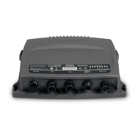
Garmin AIS 600 Manuale di istruzioni - Pagina 5
Sfoglia online o scarica il pdf Manuale di istruzioni per Attrezzatura marina Garmin AIS 600. Garmin AIS 600 13. Automatic identification system (ais) class b transponder device
Anche per Garmin AIS 600: Riferimento tecnico (42 pagine), Dichiarazione di conformità (6 pagine)

Use the following instructions to install the AIS 600 device. Details for the following steps are included in this document:
1. Select locations for the AIS components.
2. Mount the AIS 600 transceiver box.
3. Wire the AIS 600 to power.
4. Install and connect the GA 30 GPS antenna
5. Connect the AIS 600 to a VHF antenna and to an optional VHF radio
6. Connect the AIS 600 to a NMEA 2000 network or to a NMEA 0183-compatible chartplotter (optional -
7. Add a silent-mode switch or a Safety Related Message (SRM) switch (optional -
Selecting Locations for the AIS 600 Components
Use the wiring layout diagrams starting on
cables reach all components before permanently mounting any component.
Mounting the AIS 600 transceiver Box
Install the AIS 600 transceiver box below deck on a bulkhead. Select a location that is dry and protected from washdown. Ensure that the
location is well ventilated and away from objects that generate heat. Ensure that the transceiver box is at least 15
compass to avoid interference.
Needed tools
•
Drill and drill bits
•
Number 2 Phillips screwdriver
to mount the transceiver box:
1. Ensure that the chosen location is dry, protected, and well-ventilated.
2. Use the transceiver box as a template, and use a pencil to mark the holes in the four corners. Do not drill through the transceiver box.
3. Drill four
/
in. (3 mm) pilot holes.
1
8
4. Mount the transceiver box using the included M4.2 × 25 screws. You can also use bolts, washers, and nuts (not included) to mount the
transceiver box if the mounting surface is suitable.
Connecting the transceiver Box to Power
Use the AIS 600 power/data cable to connect the transceiver box to a 12 or 24 Vdc battery.
Notes:
•
Use the AIS 600 Power Wiring-Assignment Table to identify the positive and negative wires.
•
The replacement fuse on the power/data wiring harness is a 5 A, fast-acting fuse.
•
If it is necessary to extend the power wires, use 16 AWG or larger wire.
•
If your boat has an electrical system, you can possibly wire the AIS 600
directly to an unused holder on your fuse block. If you wire the AIS 600 to the
fuse block, remove the in-line fuse holder supplied with the power/data cable.
Installing the AIS 600 Power toggle
The AIS 600 can be powered on and off in one of 3 ways:
•
If the AIS 600 is connected to a NMEA 2000 network, it will toggle on and off with the NMEA 2000 network.
Note: The AIS 600 is not powered by the NMEA 2000 network, although it will turn on when it detects power on the NMEA 2000
network. You must connect the AIS 600 to power, and not just to the NMEA 2000 network.
•
If the AIS 600 is wired to a Garmin chartplotter using NMEA 0183, connect the yellow wire from the AIS 600 power/data cable to the
Accessory On wire from the chartplotter. The AIS 600 will then toggle on or off with the Garmin chartplotter.
AIS 600 Instructions
Installing the AIS 600
(page
6).
page 3
to determine how to best organize the AIS 600 components on your boat. Ensure that the
(page
7).
page
8).
Device
Device
AIS 600 power/data
AIS 600 power/data
cable
cable
AIS 600 Power Wiring-Assignment table
AIS 600 Power Wiring-Assignment table
page
7).
/
in. (40 cm) from any
3
4
Wire Color
Wire Color
Function
Function
Red
Red
Power—positive (+)
Power—positive (+)
Black
Black
Ground—negative (-)
Ground—negative (-)
