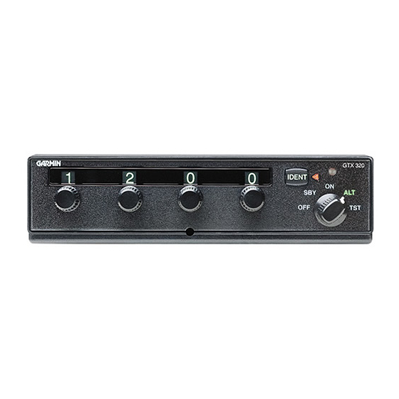
Garmin GTX 320A Manuale di installazione - Pagina 13
Sfoglia online o scarica il pdf Manuale di installazione per Radio marina Garmin GTX 320A. Garmin GTX 320A 37. Garmin gtx 320/320a transponder installation manual
Anche per Garmin GTX 320A: Manuale del pilota (4 pagine), Manuale del pilota (8 pagine), Manuale di installazione (43 pagine)

Avoid installing the unit near heat sources. If this is not possible, ensure that additional cooling is
provided. Allow adequate space for installation of cables and connectors. The installer will supply
and fabricate all of the cables. All wiring must be in accordance with FAA AC 43.13-2A.
GTX 320 units that are at Mod Level 1 must use the Mod Level 1 Rack Assembly. After Mod
Level 1, GTX 320 installations are 0.170" (4.31 mm) deeper in the panel.
A.
Assemble the connector/rack kit according to figure B2. Install the rack assembly according to the
dimensions given in figures B1. Mounting brackets are not supplied due to the wide range of
mounting configurations available. Suitable mounting brackets may be fabricated from sheet metal
or angle stock. To ensure a sturdy mount, rear support for the unit should be provided.
B.
Do not insert screws through the rear plate of the mounting tray, into the transponder. These holes
are only for use with the adapter described in paragraph 2.8.
C.
Looking at the bottom of the transponder, make sure the front lobe of the locking mechanism is in a
vertical position. This can be accomplished by using a 3/32" Allen wrench through the face plate.
D.
Slide the unit into the rack until the front lobe of the unit touches the rack. Guide pins on the back
plate will help in the proper alignment of the unit in the rack.
E.
Turn the Allen wrench clockwise until unit is secured in the rack. Continue turning until tight. Do
not overtighten the screw.
F.
To remove the unit from the rack, turn the 3/32" Allen wrench counterclockwise until it disengages
from the rack.
GTX 320/320A Installation Manual
190-00133-01
NOTES
Page 9
Rev L
