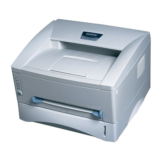
Brother HL-1030 Manuale di servizio - Pagina 6
Sfoglia online o scarica il pdf Manuale di servizio per Stampante Brother HL-1030. Brother HL-1030 8. Imprimante laser
Anche per Brother HL-1030: Elenco di riferimento delle parti (25 pagine), Manuale di configurazione rapida (16 pagine), (Francese) Manuale di configurazione rapida (16 pagine)

TABLE OF CONTENTS
2.2.3 Paper eject .................................................................................................................. 3-24
2.3
Sensors .....................................................................................................................3-24
2.3.1 Cover sensors A and B ................................................................................................ 3-24
2.3.2 Toner sensor ............................................................................................................... 3-25
2.4
Drum Unit...................................................................................................................3-25
2.4.1 Photosensitive drum .................................................................................................... 3-25
2.4.2 Primary charger ........................................................................................................... 3-25
2.4.3 Transfer roller .............................................................................................................. 3-25
2.4.5 Cleaner........................................................................................................................ 3-25
2.5
Toner Cartridge..........................................................................................................3-25
2.6
Print Process .............................................................................................................3-26
2.6.1 Charging...................................................................................................................... 3-26
2.6.2 Exposure stage............................................................................................................ 3-26
2.6.3 Developing................................................................................................................... 3-27
2.6.4 Transfer....................................................................................................................... 3-28
2.6.5 Fixing stage ................................................................................................................. 3-28
CHAPTER 4 DISASSEMBLY AND RE-ASSEMBLY.............................. 4-1
1.
SAFETY PRECAUTIONS........................................................................................4-1
2.
DISASSEMBLY FLOW............................................................................................4-2
3.
DISASSEMBLY PROCEDURE ...............................................................................4-3
3.1
AC Cord.......................................................................................................................4-3
3.2
Drum Unit.....................................................................................................................4-3
3.3
Paper Cassette ............................................................................................................4-4
3.4
Network Board (for HL-1270N only)............................................................................4-10
3.5
Front Cover................................................................................................................4-11
3.6
Top Cover ..................................................................................................................4-12
3.7
Main Cover ................................................................................................................4-13
3.8
Laser Unit ..................................................................................................................4-15
3.9
Drive Unit ...................................................................................................................4-16
3.10 Fixing Unit..................................................................................................................4-18
3.11 Base Plate .................................................................................................................4-27
3.12 Main PCB ASSY ........................................................................................................4-29
3.13 Lower Tray Relay PCB ASSY (for HL-1250/1270N only) ............................................4-29
3.14 Low-voltage Power Supply PCB ASSY.......................................................................4-30
3.15 Engine PCB ASSY / High-voltage Power Supply PCB ASSY......................................4-31
3.16 Panel PCB ASSY.......................................................................................................4-33
3.17 Solenoid ASSY ..........................................................................................................4-33
3.18 Fan Motor ASSY ........................................................................................................4-36
3.19 Toner Sensor PCB ASSY (Light Emission).................................................................4-37
3.20 Toner Sensor PCB ASSY (Light Reception) ...............................................................4-37
3.21 Paper Pick-up Roller ASSY ........................................................................................4-38
3.22 Paper Feed Roller ASSY............................................................................................4-39
3.23 Outer Chute 1 ......................................................................................................... 4-39A
4.
PACKING ..............................................................................................................4-40
iv
