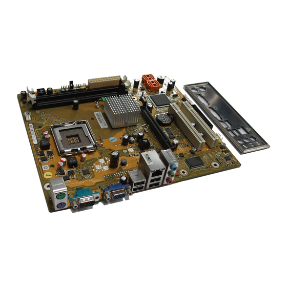
Fujitsu D2840 Descrizione breve - Pagina 15
Sfoglia online o scarica il pdf Descrizione breve per Scheda madre Fujitsu D2840. Fujitsu D2840 19.

- 1. Kurzbeschreibung des Mainboards
- 2. Anschlüsse und Steckverbinder
- 3. Prozessor Ein-/Ausbauen
- 4. Technische Daten
- 5. Hauptspeicher Ein-/Ausbauen
- 6. PCI-Bus-Interrupts - Auswahl des Richtigen PCI-Steckplatzes
- 7. BIOS-Update unter Windows mit dem Utility Deskflash
- 8. Brief Description of Mainboard
- 9. Interfaces and Connectors
- 10. Installing/Removing the Processor
- 11. Technical Data
- 12. Installing/Removing Main Memory
- 13. PCI Bus Interrupts - Selecting Correct PCI Slot
- 14. BIOS Update under Windows with Deskflash Utility
Procedure
The processor socket is covered with a protective cap to protect the spring
contacts. In the event of a warranty claim, the mainboard can only be taken back
by Fujitsu Technology Solutions with the protective cap secured!
b
Please note that, depending on the heat sink used, different heat sink
mounts are required on the mainboard.
► Depending on the configuration variant, you must pull a protective foil off the heat sink
or coat the heat sink with heat conducting paste before fitting it.
► Secure the heat sink - depending on the model - with four screws or push it into the mounts.
A26361-D2840-Z210-1-8N19, edition 1
b
a
Brief description of mainboard
► Remove the heat sink.
► Press down the lever and unhook it.
► Fold up the frame.
► Hold the processor between your thumb
and index finger and insert it into the socket
(b) so that the marking of the processor is
aligned with the marking on the socket (a).
► Press the lever downward until it is
hooked in again.
► Remove the protective cap and keep it.
English - 3
