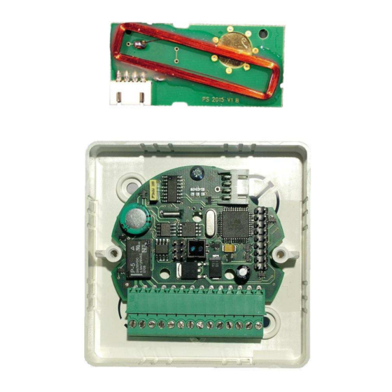
2N APS MINI ENTRYCOM Manuale d'uso e manutenzione - Pagina 6
Sfoglia online o scarica il pdf Manuale d'uso e manutenzione per Unità di controllo 2N APS MINI ENTRYCOM. 2N APS MINI ENTRYCOM 10.

Description of clips on the mother board
Connections X2
Contact
Purpose
HW address (see table on
X2.1 ÷ X2.5
the following page)
Connecting the motherboard to the lock and door contacts
Contact relay for switching the door lock is lead out to the terminal board box. For standard
locks that open in response to voltage use contacts "C" and "NO". For locks that open
when voltage disappears, while under voltage they are locked, use contacts "C" and "NC".
Lead voltage through these contacts from the power supply to the door lock.
If there is a contact on the door, which is switched when the door is closed, lead the
contacts to the clips of input 1. Contact for monitoring the status of the door (input 1) is
taken into consideration only after the first status change after switching the module on. If
this contact is left free, the relay sets the timing for the lock always for the entire pre-
defined period and alarms "Broken open" and "Door open too long" are not generated.
Function of the input 2 can be defined as leaving button or contact of the handle. Leaving
button can be used in case of "ball-ball" door configuration for opening the door from the
inside (when leaving the building). Contact of the handle can be used with "ball-handle"
door configuration.
Terminal board box
Clip
1
2
3
4
5
6
7
8
9
10
11
12
13
14
Connections X4
Contact
150
BIAS A
BIAS B
6
Purpose
Power supply + 10 ÷ 15 VDC
Power supply 0 V (ground)
Input 1
0 V
Input 2
0 V
Alarm output +5V
Wiegand DATA 0
Wiegand DATA 1
A conductor of line RS485
B conductor of line RS485
C contact relay
NC contact relay
NO contact relay
Purpose
End of RS485 line
Rest state of the line (cable A)
Rest state of the line (cable B)
