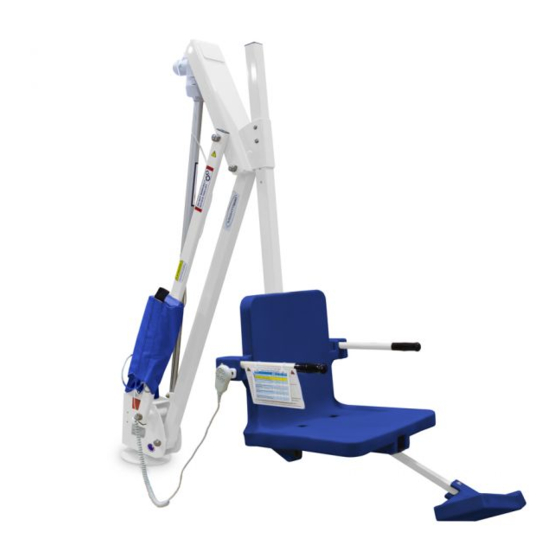
Aqua Creek Products F-MTY600-T Manuale - Pagina 7
Sfoglia online o scarica il pdf Manuale per Aiuto alla mobilità Aqua Creek Products F-MTY600-T. Aqua Creek Products F-MTY600-T 14. Pool lift

Saw-cut Retro-fi t/New construction
Mask the bottom hole of the anchor sleeve to prevent concrete from seeping in.
1.
Install rebar in the 4'-6" x 4'-6" section of the deck that will be thickened to 10". SEE
2.
FIGURES B & C.
3.
Set the bronze anchor sleeve in place. Make sure the center of the anchor sleeve
is no more than 44" from the pool's edge. Set the fi xing anchor insert 3 1/2" from the
center of the anchor sleeve. Fixing anchor may be located anywhere on the deck, as
long as it is 3 1/2" from the center of the anchor sleeve. SEE FIGURE B.
Bond the anchor sleeve according to your local code requirements by using the
4.
bonding lug and bonding screw on the side of the anchor sleeve.
Pour your concrete and fi nish the pool deck surface.
5.
Once the concrete has cured, your lift is ready to be mounted into the anchor sleeve.
6.
4'-6"
(MIN)
1" O.D. X 4"
FIXING ANCHOR
DRILLING & EPOXYING REBAR TO EXISTING SLAB
(4" MIN EMBED W/ HILTI RE500 SD OR SIMPSON SET-XP EPOXY)
IS RECOMMENDED TO RESIST DIFFERENTIAL MOVEMENTS
4'-6" SQ. X 10" DEEP CONC. FTG.
2"
W/ 4-#5 LONG & 6-#5 TRANS
(2500 PSI MIN)
CLR
10"
3"
CLR
8-AWG SOLID COPPER WIRE
(TO BONDING GRID)
1" X 4" PVC FIXING ANCHOR
BONDING LUG: BOND PER LOCAL CODE
2.19" O.D. X 6" BRONZE ANCHOR ASSEMBLY
Copyright © 2019 Aqua Creek Products All Rights Reserved
Anchor Installation:
4'-6"
12"
(MIN)
MIN
12" MIN
32" MAX
3 1/2"
(44" MAX)
4" MIN CONC.
SLAB BY OTHERS
2.19" O.D. X 6"
BRONZE ANCHOR
ASSEMBLY
3 1/2"
FIGURE B
24" MIN
POOL WALL
FIGURE C
FIGURE C
FIGURE C
Revised 4/23/19
7
