DeZurik G-SERIES Istruzioni - Pagina 6

Sfoglia online o scarica il pdf Istruzioni per Controllore DeZurik G-SERIES. DeZurik G-SERIES 19. Lift, turn and reseat used on ptw & pfw tapered plug valves
Anche per DeZurik G-SERIES: Istruzioni (7 pagine), Manuale (8 pagine), Manuale (17 pagine), Manuale (14 pagine), Manuale (12 pagine), Manuale (14 pagine), Manuale (16 pagine), Manuale (17 pagine), Manuale di istruzioni (13 pagine), Manuale (9 pagine)
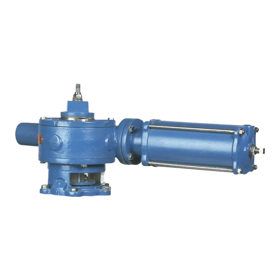
DeZurik G-SERIES Istruzioni
DeZURIK
Cylinder Operated G-Series Actuator
Adjusting Position Stops
Adjusting Closed Position Stop
On actuators without booster cylinders, the closed position stop is located in the end of the cylinder. On
actuators with booster cylinders, the closed position stop is located in the end of the booster cylinder.
See Figure 2.
Valves can be mounted with Direct or Reverse pressure.
Direct Pressure - When the higher pressure is at the end opposite the seat. See Figure 3.
Reverse Pressure - When the higher pressure is at the seat end of the valve. See Figure 3.
1. Discontinue flow and relieve pipeline pressure.
2. Back out the Closed Position set screw about 1½ turns.
Close the valve with the pressure specified in Table C and Table D for the appropriate size and
3.
pressure direction—See Figure 3
Direct Pressure (higher pressure is at end opposite the seat), use the cylinder pressure
specified in Table C and Table D for 25 psi (172 kPa) reverse pressure drop.
Reverse Pressure (higher pressure is at seat end of valve), use the cylinder pressure specified
in Table C and Table D for the amount of reverse pressure drop in your pipeline.
The pressure in Table C and Table D will provide tight shut off or minimum leakage (depending on
pressure drop) with maximum plug life. If the reverse pressure drop in the pipeline is unknown, set
closing pressure for the maximum pressure drop. Reset the closing pressure as soon as actual
pressure drop can be determined because the maximum setting decreases plug life.
4. Maintain pressure for 5 minutes to allow the plug to seat, then tighten the set screw in until it
comes into contact with the piston rod.
NOTE: Make sure the thread seal is positioned properly, and lock the setscrew in place with the jam nut.
D10022
(Continued)
Figure 3 – Pressure Direction
.
Page 6
August 2012