DFE TrueView 1100 Manuale di istruzioni - Pagina 6
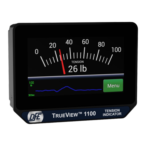
Sfoglia online o scarica il pdf Manuale di istruzioni per Strumenti di misura DFE TrueView 1100. DFE TrueView 1100 14. Tension indicator

2
INSTALLATION
2.1. DIMENSIONS
2.2
MOUNTING THE UNIT
There are three mounting choices:
1.
Din Rail Mount
rail clip to back of unit with provided mounting screws. Clip the
top of the DIN rail clip onto the top of the DIN rail and pull down
while pushing forward slightly to snap the unit onto the rail.
To remove from the DIN rail, push the device down while
pulling its bottom forward, then pull up when bottom is free.
2.
Panel Mount:
back. Insert into panel cut-out from the front. Attach panel-mount
brackets to the back of the indicator with the provided mounting
screws and tighten the assembly against the mounting panel.
3.
Pole Mount:
or smaller width and the appropriate diameter for the mounting
surface. Pass the tail end (without the nut) through one of the pockets
in the Pole Mount Adapter and out of the other, ensuring the recess
faces outwards from the pole (towards the unit). Screw Pole Mount
Adapter to unit with provided mounting screws, wrap clamp around
pole or railing and secure unit by tightening clamp.
: Compatible with 35mm DIN rail. Screw DIN
Slide panel-mount bezel over the unit from the
Unscrew a hose clamp (not provided) with a 1/2"
DIN RAIL MOUNT
PANEL MOUNT
POLE MOUNT
2
