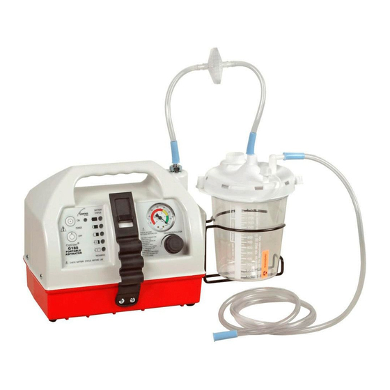
Allied Healthcare L190-GRCE Manuale di funzionamento e assistenza - Pagina 7
Sfoglia online o scarica il pdf Manuale di funzionamento e assistenza per Apparecchiature mediche Allied Healthcare L190-GRCE. Allied Healthcare L190-GRCE 14. Dc portable aspirator

4.6 BATTERY REPLACEMENT:
1.
The G180 and G180CE use a sealed lead acid battery rated at 12 VDC, 5 AMP Hour, Part Number
Su1060. The L190, L190CE, L190-GR and L190-GRCE use a sealed lead acid battery rated at 12 VDC,
3.4 AMP Hour, Part Number L200027.
2.
Remove the Case Back and Case Front from the Bottom.
3.
Remove the brown wire connection from the battery (+). Remove the green wire connection from the
battery (-).
4.
Remove the three screws that attach the battery hold down bracket to the Case Bottom.
5.
Remove the battery hold down bracket.
6.
Lift up and remove the battery carefully.
7.
Install new battery, secure with battery hold down bracket and associated screws and complete the wire
connections, brown wire to battery (+) and green wire to the battery (-).
8.
Check battery for proper operation.
9.
Discard old battery per local ordinances.
4.7 FUSE REPLACEMENT:
1.
Two 4 amp fuses located inside the power entry fuse drawer on the rear of the unit.
2.
Pull fuses out of drawer and replace only with a fuse of equal size and rating (4 amp, 250V).
3.
Replace the fuse drawer into the power entry.
4.
There is a 10 amp, 250V slow blow fuse located in the fuse holder above the power entry. To replace, use
a flat blade screwdriver to rotate the fuse holder cap 1/8 turn counter-clockwise and replace the fuse with
one of equal size and rating.
WARNING:
To help prevent fire/shock hazard, replace only with a fuse of equal size and rating.
4.8 PUMP REPLACEMENT:
1.
Remove the Case Back and Case Front from the Case Bottom.
2.
Disconnect the black and red wires leading from the pump to the wire harness connections.
3.
Remove the battery bracket.
4.
Remove the three screws and one standoff that attach the Mounting Plate Assembly to the Case Bottom.
5.
Lift up and remove the Mounting Plate Assembly from the Case Bottom.
6.
Remove the tubing and barbed fitting from the vacuum pump inlet and outlet ports.
7.
Remove the screws and washers that attach the pump to the mounting plate. These are located underneath
the mounting plate.
8.
Remove pump.
9.
Reassemble in reverse order.
4.9 PC BOARD REPLACEMENT:
1.
Remove the Case Back and Case Top from the Case Bottom.
2.
Disconnect the Wire Assembly from the connector on the back of the PC Board.
3.
Unscrew the screws that attach the PC Board to the Case Top.
4.
Remove the PC Board.
5.
Reassemble in reverse order.
4.10 SOLENOID REPLACEMENT:
1.
Remove the Case Back and Case Front from the Case Bottom.
2.
Disconnect solenoid wire from the battery (+).
3.
Disconnect the solenoid wire from the purple wire of the Wire Harness Assembly.
4.
Remove the screws that attach the Mounting Plate Assembly to the Case Bottom.
5.
Lift up and remove the Mounting Plate Assembly from the Case Bottom.
6.
Disconnect the tube that connects to the solenoid inlet port.
7.
Remove the fitting from the solenoid inlet port.
8.
Remove the screws and washers that attach the solenoid to the mounting plate.
9.
Remove the solenoid.
10. Reassemble in reverse order.
4.11 POWER SUPPLY REPLACEMENT:
1.
Remove the Case Back and Case Front from the Case Bottom.
2.
Remove the three screws that attach the battery hold down bracket to the Case Bottom.
3.
Remove the battery hold down bracket.
4.
Remove the Power Supply from the Case Bottom.
5.
Disconnect the Wire Assemblies from the Power Supply.
6.
Reassemble in reverse order.
7
