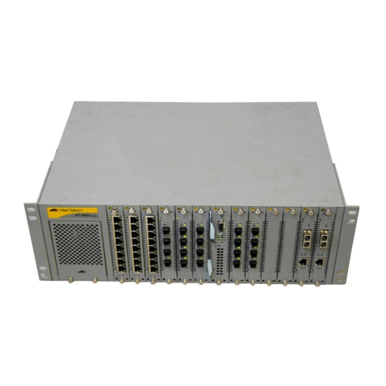
Allied Telesis AT-8400 Series Manuale di installazione
Sfoglia online o scarica il pdf Manuale di installazione per Interruttore Allied Telesis AT-8400 Series. Allied Telesis AT-8400 Series 2. Line card and power supply
blank faceplate
Anche per Allied Telesis AT-8400 Series: Manuale di installazione (2 pagine)

Electrical Safety and Emission Statement
Standards: This product when meets the following standards when installed in compliant host
equipment:.
U.S. Federal Communications Commission
RADIATED ENERGY
Note: This equipment has been tested and found to comply with the limits for a Class A digital device pursuant
to Part 15 of FCC Rules. These limits are designed to provide reasonable protection against harmful
interference when the equipment is operated in a commercial environment. This equipment generates, uses,
and can radiate radio frequency energy and, if not installed and used in accordance with this instruction
manual, may cause harmful interference to radio communications. Operation of this equipment in a residential
area is likely to cause harmful interference in which case the user will be required to correct the interference at
his own expense.
Note: Modifications or changes not expressly approved of by the manufacturer or the FCC, can void your right
to operate this equipment.
Industry Canada
This Class A digital apparatus meets all requirements of the Canadian Interference-Causing Equipment
Regulations.
Cet appareil numérique de la classe A respecte toutes les exigences du Règlement sur le matériel brouilleur du
Canada.
Emission
FCC Class A, EN55022 Class A, VCCI Class A, C-TICK
WARNING:
In a domestic environment this product may cause radio interference in which case the user
may be required to take adequate measures.
Immunity
EN55024
Electrical Safety EN60825, EN60950 (TUV), UL60950 (UL/cUL)
4
AT-8400 Fan Replacement
Installation Guide
For use with the AT-8400 Chassis
Overview
The AT-8403 fan is designed for an AT-8400 Chassis. See the illustration
below. For proper operation, ATI requires two AT-8403 fans-- one in the Fan A
slot and another in the Fan B slot. Both slots are located at the rear of the AT-
8400 Chassis. In addition, both fans are field replaceable. This quick
installation guide provides instructions for replacing the fans.
Related Documents
For complete details regarding the features, functions, and installation
instructions for the AT-8400 Chassis, refer to the AT-8400 Series Switch
Reference Guide (part number 613-50399-00) which is available from the
Allied Telesyn web site at www.alliedtelesyn.com.
PN 613-50419-00 Rev A
A T - 8
4 0 3
010425
