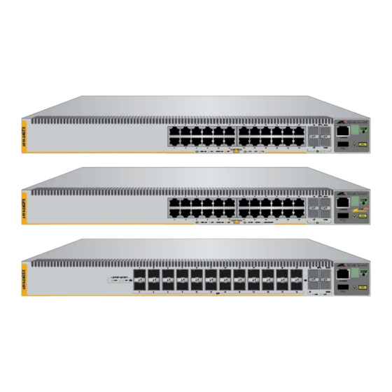
Allied Telesis AT-x510-52GTX Manuale di installazione - Pagina 17
Sfoglia online o scarica il pdf Manuale di installazione per Interruttore Allied Telesis AT-x510-52GTX. Allied Telesis AT-x510-52GTX 20. Gigabit ethernet switches
Anche per Allied Telesis AT-x510-52GTX: Informazioni sul prodotto (8 pagine), Manuale di installazione (20 pagine)

Stacking Slots
Two SFP+ slots can be used with special stacking transceivers to create a
VCStack of up to four switches that operate as a virtual switch. Here are
the basic features of the stacking slots on the x510 Series switches:
LEDs
Here are the port LEDs:
Installation
Here are the installation options for the switches:
Options
MAC Address
Here are the basic features of the MAC address tables of the switches:
Table
Management
Here are the management software and interfaces:
Software and
Interfaces
Management
Here are the methods for managing the switches:
Methods
Note
SFP+ slots 27 and 28 on the AT-x510-28GTX Switch and slots 51
and 52 on the AT-x510-52GTX Switch are initially configured as
stacking slots for the VCStack feature. If you intend to use the switch
as a stand-alone unit, you must disable the VCStack feature before
you can use the slots with standard SFP or SFP+ transceivers. The
configuration instructions are provided later in this guide, in
"Configuring the Switch for Stand-alone Operations" on page 62.
Two stacking slots per switch
40Gbps stacking bandwidth
Duplex mode and link/activity LEDs for the twisted pair ports
Link/activity LEDs for the SFP+ slots
Stack ID number LED
eco-friendly button turns off the LEDs to conserve electricity
19-inch equipment rack
Desk or tabletop
Storage capacity of 16,000 dynamic MAC address entries
Storage capacity of 256 static MAC address entries
Automatic learning and aging
AlliedWare Plus Management Software
Command line interface
Web browser interface
Local management through the Console port
Remote Telnet and Secure Shell management
x510 Series Installation Guide for Stand-alone Switches
17
