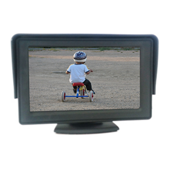
AVS RM70M Manuale di installazione - Pagina 4
Sfoglia online o scarica il pdf Manuale di installazione per Monitor AVS RM70M. AVS RM70M 4.
Anche per AVS RM70M: Manuale di installazione (5 pagine)

AVS RM70CQUAD / RM90CQUAD
The AVS RM70CQUAD/RM90CQUAD can display up to 4 cameras in a split screen, either any channel full screen, 2/3/4-way split.
The channels can be switched manually using the buttons on the front panel or by remote or can be controlled by each channel's input wire
e.g. connect the blue wire to the left turn indicator trigger wire and mount camera 3 on the left side of the vehicle. When the left indicator
turns on the monitor will display the left side camera. Do not connect any input control wire to permanent power as this will lock the
display to that channel and may damage the monitor.
WIRE COLOUR
FUNCTION
RED
+12/24v ACC supply
BLACK
Earth
GREEN
Switches display to CH2 REVERSE
BROWN
Switches display to CH1/FORWARD
BLUE
Switches display to CH3/LEFT
GREY
Switches display to CH4/RIGHT
CH2 (REV) 4 pin
CH2 camera input & power 12v out
connector
CH1 (FWD) 4 pin
CH1 camera input & power 12v out
connector
CH3 (L) 4 pin
CH3 camera input & power 12v out
connector
CH4 (R) 4 pin
CH4 camera input & power 12v out
connector
BUTTON
POWER
MODE
MENU
(RM70CQUAD access
through remote only)
CH1/<
CH2/>
CH3/Ú
CH4/Ù
MENU OPTIONS
PICTURE
VOLUME
MIRROR
SYSTEM
CLOCK
FUNCTION
Power on/off
Switch between – full screen – dual screen – 3 way split even – 3 way split left – 3 way split right – 4 way
split left & right – 4 way split ¼ screen
MENU –push to enter menu and scroll through functions. See options below
Manually switch to CH1 camera or adjust left
Manually switch to CH2 camera or adjust right
Manually switch to CH3 camera or adjust down
Manually switch to CH4 camera or adjust up
FUNCTION
Adjust brightness/contrast/colour/tint/reset
Adjust volume
Camera 1 – 4 mirror option – ON>/OFF<
Language/RU (rotation) rotates monitor display for upside down mounting (RM70CQUAD only)
Cam 1-4 delay (default 3 sec, adjustable 0-10 sec). Adjusts time display holds on channel after signal
removed from green, brown, blue or black wire.
CONNECT TO
Appropriately fused +12/24v switched ignition on supply
Good earth source e.g. vehicle body/chassis
Reverse signal/vehicle reverse light wire (+12/24v)
Forward camera switch (+12/24v)
Left turn indicator or switch (+12/24v)
Right turn indicator or switch (+12/24v)
4 pin camera cable. Monitor will switch to display this input when a
signal is detected on GREEN wire.
4 pin camera cable. Monitor will switch to display this input when a
signal is detected on BROWN wire.
4 pin camera cable. Monitor will switch to display this input when a
signal is detected on BLUE wire.
4 pin camera cable. Monitor will switch to display this input when a
signal is detected on GREY wire.
