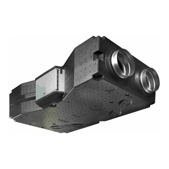
2VV VENUS AirGENIO Comfort Manuale di installazione - Pagina 10
Sfoglia online o scarica il pdf Manuale di installazione per Cappa di ventilazione 2VV VENUS AirGENIO Comfort. 2VV VENUS AirGENIO Comfort 15.
Anche per 2VV VENUS AirGENIO Comfort: Manuale di avvio rapido (16 pagine)

6. INSTALLATION
6.5.ELECTROINSTALLATION
AND ELECTRICAL FITTINGS
ATTENTION
The main electrical supply must be turned off prior to any
•
interference with the internal parts of the ventilation unit!
The electro installation of the ventilation unit must be
•
implemented according to the technical documentation
issued by a qualified electro engineer. The actual installa-
tion can be carried out by a professional educated in the
electro field. The manual instructions must be observed
as well as the valid national regulations and directives.
The electrical charts featured on the product have a
•
higher priority than the charts included in the manual!
Prior to installation, check if the marking of the termi-
nals conform to the electrical chart for connection. In the
event of any doubts, contact your supplier and under no
circumstances should you connect the ventilation unit.
The unit must be connected to the power supply using in-
•
sulated fixed and temperature resistant cable according
to the diameter and the relevant national regulations and
directives.
Any interference and amendments into the internal co-
•
nnection of the unit are prohibited and can lead to a loss
of the warranty service.
Correct unit functioning is guaranteed only with original
•
fittings.
6.5-1 Electrical power cord
The connecting terminal board of the electrical power cord is
positioned in the regulation box.
TECHNICAL INFORMATION
The electrical parameters are stated on the manufacturer's
•
label.
Product type
U
= power supply
F
= frequency
N
= ventilator rpm
Ph
= number of phases
Av
= air flow
Serial number
10
ver.1 06-04-20
I
= total current
P
= power input
M
= weight
IP
= el. protection
Ver = version
2VV. Creating innovative solutions for you and your business since 1995.
The heat recovery unit must be connected using the TN-S
system which means that the neutral wire must always be
connected.
All electrical circuits into the heat recovery unit must be co-
nnected via a protective power circuitbreaker according to
the current and type. The distance in between the open con-
tacts must be bigger than 3mm.
JHeat recovery unit must be connected in such a manner so
it can be disconnected from the power supply via a single
element. Table of the minimum dimensioning of the circuit
breakers according to the type of heat recovery unit.
Recommended circuit breakers:
Circuit breakers
HRV14EC
HRV15EC
HRV30EC
HRV50EC
HRV70EC
6.5-2 Electrical fittings
Connect the unit electrical fittings to the terminal inside the
regulator box exactly according to the el. diagram for conne-
ction and according to the markings of the terminals.
DO NOT MISS!
The connection diagram is glued to the internal side of the
•
removable lid of the regulator box.
Each element must be connected using an original cable or
•
cable as per the specification for each element.
To open the lid of the regulator box you will need TORX20 key.
•
See picture.
10A, 1ph
10A, 1ph
10A, 1ph
16A, 1ph
16A, 1ph
TORX 20
