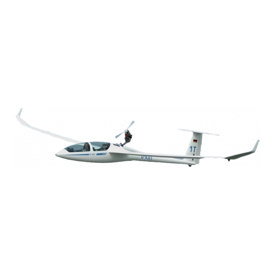
DG Flugzeugbau DG-1000T Manuale di manutenzione - Pagina 6
Sfoglia online o scarica il pdf Manuale di manutenzione per Aerei DG Flugzeugbau DG-1000T. DG Flugzeugbau DG-1000T 10. & motorglider
Anche per DG Flugzeugbau DG-1000T: Manuale di riparazione (16 pagine)

Maintenance Manual DG-1000T
C Removal of the lower landing gear fork 10Fw11/1
1.
Remove the main wheel see A.
2.
Retract the landing gear.
Warning: The landing gear will retract by itself when unlocked by the force of
the gas spring!
3.
Disassemble the gas spring from the left side of the undercarriage box see 4.5.0.
4.
Extend the landing gear again.
5.
Remove the 2 bolts M10 LN9037 which connect 10Fw11/1 to 10Fw10/1.
(Mark the bolts and don't mix them up when reassembling the parts).
6.
Remove fork 10Fw11/1.
D Removal of the spring legs (parts 10Fw16 and 10Fw17)
1.
Remove the main wheel see A.
2.
Remove the bolts M8×62 LN9037 which connect the spring legs to the fork
10Fw10/1.
3.
Remove the spring legs.
4.
If it is necessary to disassemble the spring leg to exchange a component, the
reassembly must be done according to drawing 10Fw2 (enclosed to this
manual).
E Removal of the struts 10Fw14/1
1.
Remove the main wheel see A.
2.
Retract the landing gear.
Warning: The landing gear will retract by itself when unlocked by the force of
the gas spring!
3.
Disassemble the gas spring from the left side of the undercarriage box see 4.5.0.
4.
Extend the landing gear again.
5.
With TN1000/13 executed, standard from ser. no. 10-133 on:
Remove the positive locking device for the extended landing gear position.
6.
Remove the 2 bolts M8×65 LN9037 which connect the struts to fork 10Fw10/1.
7.
Remove the 2 bolts M8×40 LN9037 which connect the struts to the rear fork
10Fw12/2.
With TN1000/13 executed, standard from ser. no. 10-133 on:
bolt M8x40 LN9037 on the right hand side and bolt M8x42 LN9037 on the left
hand side
8.
Remove the struts.
Issued: February 2008
TN 1000/13
F Removal of the front fork 10Fw10/1
1. Remove the baggage compartment floor and the rear cover of the
baggage compartment.
2. Remove the main wheel see A.
3. Remove the lower fork 10Fw11/1 see C.
4. Remove the spring legs see D.
5. Remove the struts see E.
6. Remove the nut M12 from the left hand side of the axle 10Fw10/2. Shift
the axle towards the fuselage wall. Mark the head of the axis at the
outside fuselage wall (e.g. by illuminating this area from the inside) and
drill a dia. 24 mm hole through the fuselage wall. Insert a bolt with
thread M8 into the head of the axle (from ser. no. 10-7 on) to pull out the
axle through the hole.
7. Remove the front fork 10Fw10/1.
G Removal of the rear fork 10Fw12/2
1. Remove the main wheel see A.
2. Retract the landing gear.
Warning: The landing gear will retract by itself when unlocked by the
force of the gas spring!
3. Disassemble the gas spring from the left side of the undercarriage box
see 4.5.0.
4. Extend the landing gear again.
5. Remove the 2 bolts M8×40 LN9037 which connect the struts to the rear
fork 10Fw12/2.
With TN1000/13 executed, standard from ser. no. 10-133 on:
bolt M8x40 LN9037 on the right hand side and bolt M8x42 LN9037 on
the left hand side.
6. Remove the 2 bolts M6×24 LN9037 which connect the struts to the rear
fork 10Fw12/2, don't change the length of the struts and don't mix up
right and left strut.
7. Remove the nut M12 from the left hand side of the axle 10Fw12/1. Shift
the axle towards the fuselage wall. Mark the head of the axis at the
outside fuselage wall (e.g. by illuminating this area from the inside) and
drill a dia. 24 mm hole (ser. no. 10-1 up to 10-6) resp. dia. 20mm (from
ser,no. 10-7 on) through the fuselage wall. Insert a bolt with thread M8
into the head of the axle (from ser. no. 10-7 on) to pull out the axle
through the hole.
8. Remove the fork 10Fw12/2.
4.7
Issued: February 2008
Maintenance Manual DG-1000T
TN 1000/13
4.8
