AVT 1916 Manuale di avvio rapido
Sfoglia online o scarica il pdf Manuale di avvio rapido per Interruttore AVT 1916. AVT 1916 4. Configurable 4-channel switch

Configurable 4-Channel Switch
kits
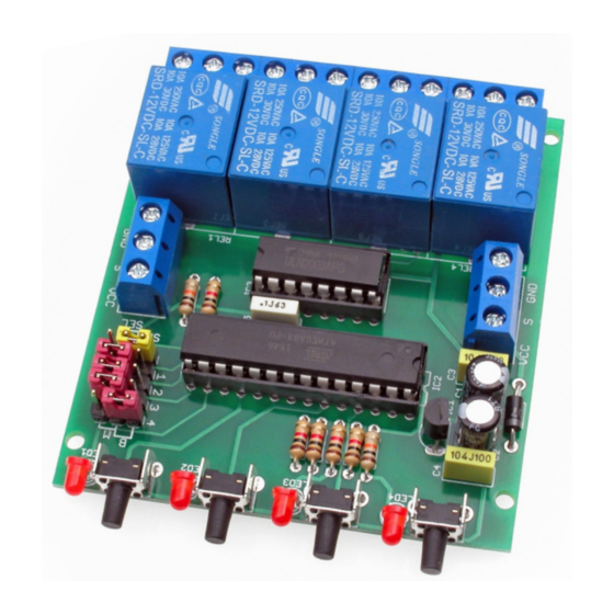
A configurable 4-channel switch circuit, allowing the
attached devices to be controlled in any way. Each
output can operate in monostable, bistable and
dependent modes, and due to the synchronisation
output and input, it is possible to link multiple such
switches together.
Circuit description
Schematic diagram of the switch is shown in Figure 1.
It must be supplied with 12VDC. Operation of the
switch is controlled by an Atmega8 microcontroller.
The ULN2003A circuit is used to power relays.
LED1...LED4 indicate which relay is energised. Relays
are switched using the S1...S4 buttons.
The "MODE" jumper is used to select the operation
mode, while the way of switching on a particular
relay is made using jumpers 1...4, switching them to
the "B" position - bistable operation or "M" -
monostable
operation.
The "MODE" jumper set in "SW" mode configures
the device to operate in the switch mode with the
possibility of setting any channel as a monostable
switch ( jumper in "M" position - relay
is switched on as long as the button is held down) or
Specifications
• 3 operating modes: monostable, bistable and
dependent
• multiple such switches can be connected together
• independent configuration of each of the four outputs
• output circuit: 4 relays 230 VAC / 10 A (NC/NO)
• supply: 12 VDC
• board size: 68×75 mm
bistable ( jumper in "B" position - each time the
button is pressed, the relay changes to the opposite
state). In the next mode, the switch can operate as a
dependent. To activate this function, switch the
"MODE" jumper to the "SEL" position. In this mode,
the 'S' sync input is activated and there is a low level
on this line every time a button is pressed. This
causes all relays to switch off and only the currently
selected relay to switch on. In addition, it is possible
to deactivate dependent operation for a channel in
this mode. It is then necessary to move the selected
jumper to the "B" position - from then on, each press
of the button will change the state of the assigned
relay to the opposite without affecting the other
channels, which will continue to operate in a
dependent manner.
PDF
DOWNLOAD
ASSEMBLY DIFFICULTY
1
