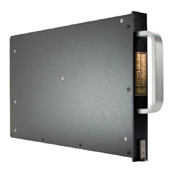
Avtech CSD-714 Selcal Manuale di installazione - Pagina 14
Sfoglia online o scarica il pdf Manuale di installazione per Convertitore multimediale Avtech CSD-714 Selcal. Avtech CSD-714 Selcal 20.

- 1. Table of Contents
- 2. Description
- 3. Operation
- 4. Specifications
- 5. Installation
- 6. Installation Testing
- 7. Equipment and Accessory Part Numbers
- 8. Notes for Installation Figures
- 9. Figure 1 - Wiring Diagram
- 10. Figure 2 - Outline Drawing
- 11. Figure 3 - Code Programming
- 12. Figure 4 - 20 Db Attenuator
- 13. Figure 5 - Annunciator Output Circuits
CSD-714 Installation and Operation Manual
If manual reset is desired, they may all be tied together and grounded through a normally open,
momentary contact switch. The SELF-TEST input (Pin MP3D) is activated by grounding it
momentarily. All of these inputs are considered grounded when the voltage on the pin is less than
3.5 volts and are open when it is above 8 volts. Internally they are connected to 10 VDC through a
4700 ohm resistor and will source approximately 2 milliamps when grounded.
Note 5 - INTERRUPT and NON-INTERRUPT ARINC OUTPUTS -- See Figure 5
The INTERRUPT and NON-INTERRUPT lines have both IN and OUT lines. The IN lines
connect to emitters of internal transistors whose collectors are connected to the associated OUT
line. When a SELCAL is decoded, the NON-INTERRUPT transistor will turn on and stay on
until all channels have been reset. The INTERRUPT transistor will
be turned on and off at a 1/2 second on, 1/2 second off rate until all channels have been reset. The
IN and OUT lines are diode isolated to prevent damage and sneak circuits and require that the
OUT line be more positive in voltage than the IN line for current to flow. Don't blame us for this
nomenclature, that's the way ARINC defined it. In most installations, the INTERRUPT lines are
used to flash the annunciator lamps by connecting the LIGHTS IN line (Pin MP8A) to the
INTERRUPT OUT line (Pin MP4D) and grounding the INTERRUPT IN line (Pin MP4C) as
shown in Figure 5. The chime is activated by connecting its control to the NON-INTERRUPT
OUT line (Pin MP4B) and grounding the NON-INTERRUPT IN line (Pin MP4A).
Note 6 - AUDIO SOURCE SELECTION
The CSD-714 has two or five decoder channels which are configured to monitor up to two or five
inputs, respectively. Each input presents a nominal 10,000 ohm input impedance, and is
transformer coupled and isolated from the other inputs.
The CSD-714 MUST be connected to the dedicated SELCAL output of HF receivers if at all
possible, since the Clarifier function of the HF affects the frequency of the normal audio output
and will cause the SELCAL signals to be off frequency. If the HF does not have a SELCAL
output normal audio output may be used, however the HF must then be operated in AM mode
whenever a SELCAL signal is expected. It will not receive the call otherwise. If the SELCAL
output is not used, verify that the audio level is within the CSD-714 input level rating.
Audio input for the CSD-714 may be obtained from the SELCAL output or the squelched audio
output of the VHF communication radios to be monitored. If the SELCAL output is used, it
normally is within the input levels specified for the CSD-714 but should be verified by consulting
the radio specifications.
1
23-21-01
June 1995
Seattle, WA USA
Rev 1
Page 8
