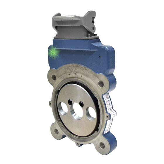
Avtron AV67 Manuale di istruzioni - Pagina 2
Sfoglia online o scarica il pdf Manuale di istruzioni per Convertitore multimediale Avtron AV67. Avtron AV67 10. 4 1/2 inch c-face mount modular

NOTE
THIN-LINE III
directly replaces THIN-LINE II
ITM
THIN-LINE
models. THIN-LINE III models have Rev
TM
Code BA or later. Special option 4xx selects an alternate
PPR code defini tion. Example: PPR Code 0, Special
Option Code 401 = 1270 PPR (Left), No Right Output.
INSTALLATION
Installation and removal videos for the AV56A/67/85/115 are available
on Avtron's web site. Refer to the back page of these instructions for
outline and mounting dimensions. The motor must comply with 1998
NEMA MG 1, section 4, for tolerances on diameters and runout for
shafts and accessory faces. Axial float or endplay must be less than
±0.050".
In preparation for installing the Model AV56A encoder, it is first
necessary to clean both the accessory motor shaft and the mounting
face. These surfaces must be inspected and any paint, burrs, or other
surface imperfections removed.
Installation procedures should be performed only by qualified
personnel. Safety precautions must be taken to ensure machinery
cannot rotate and all sources of power are removed during installation.
ROTOR INSTALLATION
The motor shaft must project at least 0.63" from the motor face. For
set screw rotors only: Apply anti-seize compound to the motor shaft.
For all rotors: Slide the rotor onto the shaft with the marking "Motor
side" facing in, (toward the motor face). The rotor centerline must
match the sensor centerline. To accomplish this, use the rotor locating
gauge (A28503) and slide the rotor onto the shaft until it is in the
proper position as shown in Figure 1. If a guage is not available, use
the stator housing alignment grooves as shown in Figure 3.
ELECTRICAL
A. Operating Power (Vin)
1. Volts ........................5-24 VDC
2. Current ...................80mA, each output, no load
B. Output Format
–
1. 2O / & Comp ...........A,A
2. Marker ....................1/Rev, Z,Z
C. Signal Type .................Incremental, Square Wave, 50 ±10% Duty Cycle.
D. Direction Sensing .......O / A leads O / B for CW rotation as viewed from the
..................................
back of the tach looking at the non-drive end of the
.................................
motor.
E. Phase Sep. .................15% minimum
F. Frequency Range .......@5V, @1m cable, 250 kHz Max
.................................
@24V, @300m cable, #8 output, 45 kHz Max
G. PPR .............................4-50000
H. Line Driver Specs .......See table
I. Connectors .................See connector options on page 1
J. Integral LED Indicator ..GREEN: power on, unit ok. RED: alarm on
.................................
ORANGE: wiring fault
MECHANICAL
A. Rotor Inertia:...............0.17-0.36 Oz. In. Sec.
B. Acceleration:...............5000 RPM/Sec. Max.
C. Speed: .........................5400 RPM Max.
D. Weight: ........................2-3 lbs [0.9kg to 1.36kg].
E. Sensor to Rotor
Air Gap (nominal):.......0.021" [0.58mm]
Tolerance: ...................0.015" [0.38mm]
F. Rotor Axial Tolerance .±0.050" [±1.27mm]
ENVIRONMENTAL
Solid cast aluminum stator and rotor
Fully potted electronics, protected against oil and water spray
Use "W" cable option on IP66/67 applications
V-Ring seals provided on through shaft covers
Operating Temperature: ........... -40 to 100°C, 0-100% condensing humidity
Vibration: 18 g's
Shock: 1 meter drop test
and
TM
SPECIFICATIONS
–
, B,B
(differential line driver)
–
2
STANDARD CAM SCREW ROTOR INSTALLATION
Turn the cam screws of the rotor in the directions shown on the rotor
to engage the cams. Tighten to 50-60 in-lb [5.6 - 6.8 N-m] (See Figure
2) using the 3mm hex wrench. Total cam screw rotation will be less
than one turn.
CAUTION
Do not adjust the cam screws before motor shaft
mounting; bottoming out the screws, or backing them
out excessively, can lead to insufficient shaft holding
force. Thread locker is preapplied on the cam screws.
LARGE BORE SET SCREW ROTOR INSTALLATION
Apply thread lock er to the rotor set screw holes, preferably from the
inside of the rotor bore before mounting. Tighten the rotor set screws
to 15 in-lb [2 N-m] using the 2mm T-handle hex wrench.
CAUTION
Use only a T-handle or torque hex wrench to tighten
set screws; using a right angle wrench will not provide
enough holding force, and the rotor may slip.
STATOR HOUSING INSTALLATION
The stator housing is attached to the motor using four socket head cap
screws (4) 3/8"-16, locating on a 5.88" bolt circle. Longer bolts (not
included), are required for sandwich installation between a motor and
a brake. Install the four mounting bolts using thread locker and torque
to approximately 20-30 ft lbs [27 to 40 N-m] using the 5/16" T-handle
hex wrench.
LINE DRIVER OPTIONS
Electrical Specifications
Input Voltage
Nom Output Voltage
Line Driver
Output Resistance Typ
Maximum Peak Current
Maximum Average
Current
Voh Typ
Vol Typ
Cable Drive Capacity
Reverse
Voltage
Short
Protection
Circuit
Transient
Power to A,
Gnd to A/
+V(out)
Alarm
Alarm*
LED
Marker
*Alarm not available on connector option "G" (Northstar
** Electrical specifications for THIN-LINE III model (rev BA or later), consult
Nidec Avtron for earlier model specifications.
AV56A
2
LINE DRIVER OPTIONS
6
8
9
5-24
5-24
5-24
5-24
5-24
5
7272
Hx
7272
13
75
13
1500
3000
1500
120
250
120
V
V
V
-1
-1
-1
IN
IN
IN
0.2 @ 10mA line
0.5
0.5
current
1000' @ 5V
500' @ 12V
1000'
1000'
200' @ 24V
yes
yes
yes
yes
yes
yes
yes
yes
yes
yes
yes
yes
Output voltage equal to input voltage.
Open collector, normally off, goes low on alarm,
sink 100mA max, 50VDC max
Green=power on, Red=Alarm, Orange=Wiring Error
One per revolution. Pulse width
approximately 2°
compatible pinout)
TM
Units
VDC
VDC
ohms
mA
mA
VDC
VDC
feet
