Dell Networking S5000 Manuale introduttivo - Pagina 6
Sfoglia online o scarica il pdf Manuale introduttivo per Interruttore Dell Networking S5000. Dell Networking S5000 37. Data center switch
Anche per Dell Networking S5000: Manuale di installazione (50 pagine), Manuale di configurazione (12 pagine), Manuale di configurazione (17 pagine)
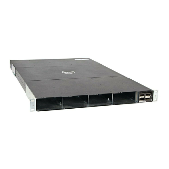
Figure 2. S5000 I/O Panel
1. Slot 0 (supports Ethernet and Fibre Channel
modules)
2. Slot 1 (supports only Ethernet modules)
3. Slot 2 (supports only Ethernet modules)
NOTE: The LED displays for the system status are on both sides of the chassis. The fan and power status LEDs are
on the Utility panel.
Utility Panel
The Utility panel side of the platform contains the fan and power modules.
Figure 3. S5000 Power Supplies and Fan Modules
1. Slot 0 (for PSU 0)
2. Slot 1 (for Fan Module 0)
3. Slot 2 (for Fan Module 1)
Power Supplies
The S5000 supports two hot-swappable PSUs.
NOTE: The PSUs must be installed at the customer site.
The S5000 has SKUs that support the following configurations:
•
AC PSU with fan airflow from I/O to Utility
•
AC-R PSU with fan airflow from Utility to I/O
•
DC PSU with fan airflow from I/O to Utility
•
DC-R PSU with fan airflow from Utility to I/O
6
4. Slot 3 (supports only Ethernet modules)
5. Four 40GbE QSFP+ ports (each port ALSO supports
4 × 10GbE mode)
4. Slot 3 (for PSU 1)
5. Grab Handles