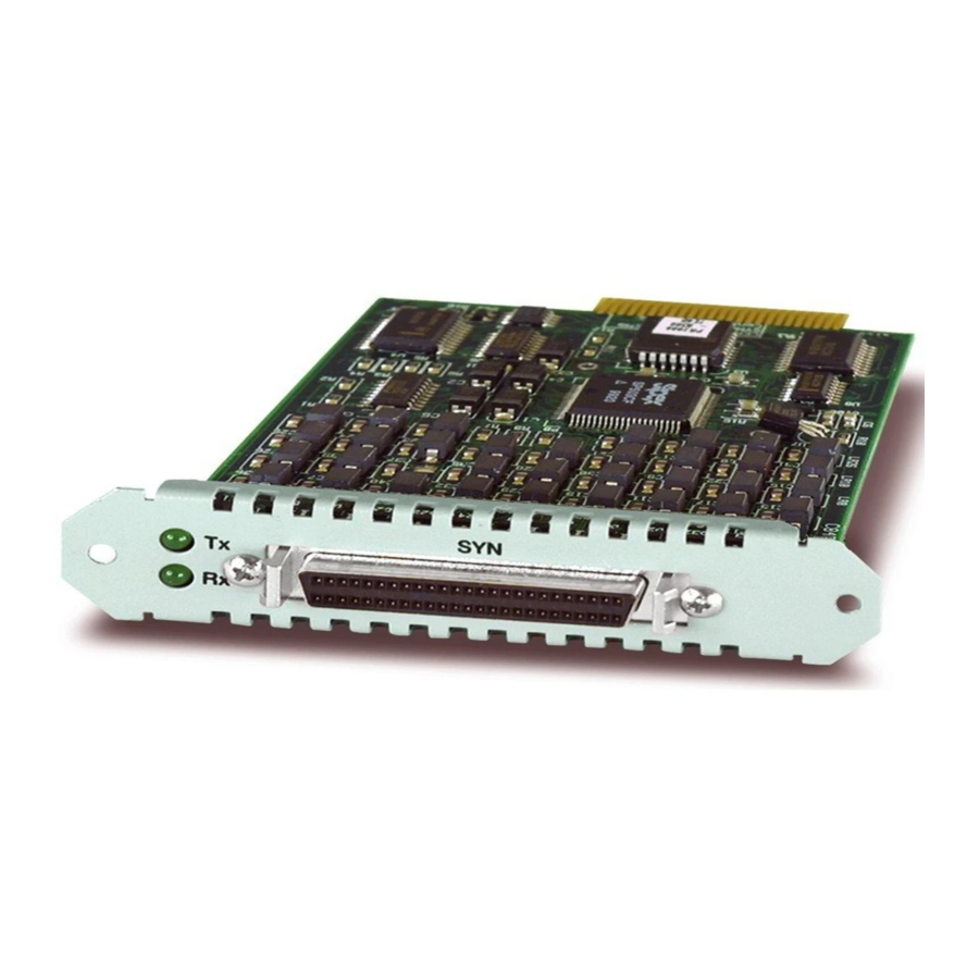
Allied Telesis AT-AR021 BRI-T Manuale di installazione - Pagina 6
Sfoglia online o scarica il pdf Manuale di installazione per Scheda di rete Allied Telesis AT-AR021 BRI-T. Allied Telesis AT-AR021 BRI-T 13. Port interface card
Anche per Allied Telesis AT-AR021 BRI-T: Manuale di installazione e sicurezza (8 pagine)

Installation and Safety Guide
Installing a PIC
This section describes the procedure for installing a PIC. You should also follow this
procedure, in particular the safety procedures and warnings, when replacing or
removing a PIC.
Caution You cannot install PICs into an AT-AR040 NSM that has power applied to
it. This includes NSMs that have been deactivated using the hot swap button, but not
physically removed from the switch or router. To ensure that all power is removed
from the NSM bay, you must either physically remove it from the switch or router
using the hot swap method, or disconnect all power sources to the switch or router.
1.
Read the safety information.
For safety information, see the Installation and Safety Guide shipped with your
switch or router. You can also download the complete documentation for your
switch or router from www.alliedtelesis.com/support/software/.
2.
Gather the tools and equipment you will need.
A medium-sized flat-bladed screwdriver may be useful when loosening the PIC
thumbscrews. You should also have any cables required for connecting the PIC
to a wide area network or other network devices.
3.
Remove power to the switch or router.
Warning Do not install a PIC into an NSM bay or PIC bay base unit without
first removing power from the switch or router. Be sure to disconnect both the
main power supply and any attached redundant power supply. Installing a PIC
with the switch or router powered ON can damage the PIC, NSM and base unit.
4.
Remove all TNV connections to existing PICs.
Warning Remove any cables attached to the external WAN ports of the
AT-AR020, AT-AR021 and AT-AR027 PICs, as these supply TNV into the
switch or router. Dangerous voltages may be present on some parts of the
board, even if the switch or router is powered OFF.
5.
Install the AT-AR040 NSM if required.
Use the installation instructions in the Network Service Module Installation and
Safety Guide to install an AT-AR040 NSM.
6.
Remove the PIC bay faceplate, NSM PIC bay faceplate, or existing PIC.
Loosen the thumbscrews to remove the faceplate or PIC. Keep the faceplate
for future use. If you remove the PIC, replace the faceplate to prevent dust and
debris from entering the switch or router and to maintain proper airflow.
5
