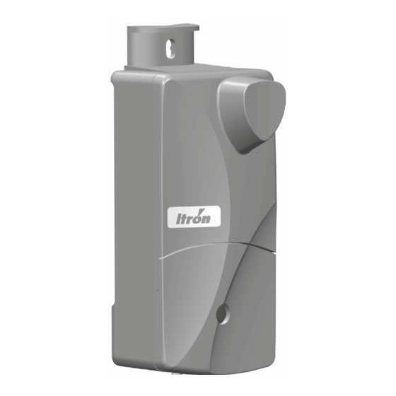
Allmess ITRON EquaScan pMIURF Istruzioni di montaggio e programmazione - Pagina 7
Sfoglia online o scarica il pdf Istruzioni di montaggio e programmazione per Unità di controllo Allmess ITRON EquaScan pMIURF. Allmess ITRON EquaScan pMIURF 8. Pulse meter radio module

MODULE PARAMETERS
The following specific parameters related to the pulse meter are possible: Other general functional parameters from
EquaScan pulse meter RF module are possible:
• Setting the internal clock.
CAUTION: Changing the date has a direct influence on
the fixed date function!
• Setting the billing month (fixed date month).
• Setting the meter Customer serial number.
• Activating / deactivating the radio encryption.
• Setting an inductive password.
• Resetting / deleting alarms and registers:
- Removal / tamper alarm
- Monthly history
- Reverse flow register
- End-of-year indexes
You can find more precise information in the user´s
manual or the EquaScan software.
Electrical signals of the pMIU
Wire color
Marking on the Device
Black
GND
Green
TAMP
Yellow
DIR/DATA
Red
REED VCC
White
OPEN COLLECTOR
Brown
GND
All external circuits must be SELV (Safety Extra Low Voltage) and be with limited Power Source following chapter 2.2 of
IEC60950-1:2005+/A1:2010 and 2.5 of EN60950-1:2006+/A11:2009+/A1:2010+/A12:2011. All in- and outputs should be
connected on potential-free contacts suitable for dry circuits.
Connection Wires: The wire section of the individual contact is AWG24 or 0.2 mm
Meter w. Reed Switch
GND
GND - Reed
OPEN Collector
(input 1 statistic)
REED
Reed Switch
(input 1 reed)
DIR
TAMP
GND
Gas, Electric Meter w. P0 Interface
GND -
GND
P0 Interf.
OPEN Collector
(input 1 statistic)
P0 Signal
REED
(input 1 reed)
DIR
TAMP
GND
RF
Signal description
Ground (0V)
Cable cut tampering signal & pMIU
nected to GND (0V) of meter
pMIU
pulse input : Signal for the Flow Direction/Data (logic high =
RF
forward) or useable as a secondary pMIURF pulse input ( e.g.: CF Echo
for Rep-Volume)
pMIU
pulse input : Type «Reed switch»
RF
pMIU
pulse input : Type «Open Collector» (solid state)
RF
Ground (0V)
CF Echo Rep E/V
GND
OPEN Collector
(input 1 statistic)
REED
(input 1 reed)
DIR
TAMP
GND
Cyble sensor (2 wires)
GND
OPEN Collector
(input 1 statistic)
REED
(input 1 reed)
DIR
TAMP
GND
activation of RF system when con-
RF
.
2
Cyble sensors (3 wires)
GND - E / 16
GND
REP E / 17
OPEN Collector
(input 1 statistic)
REED
(input 1 reed)
REP V / 19
DIR
GND - V / 18
TAMP
GND
Cyble sensor (5 wires)
GND
GND
Out LF
OPEN Collector
(input 1 statistic)
REED
(input 1 reed)
DIR
TAMP
GND
GND
Out LF
TAMP
GND
Out LF
DIR
TAMP
