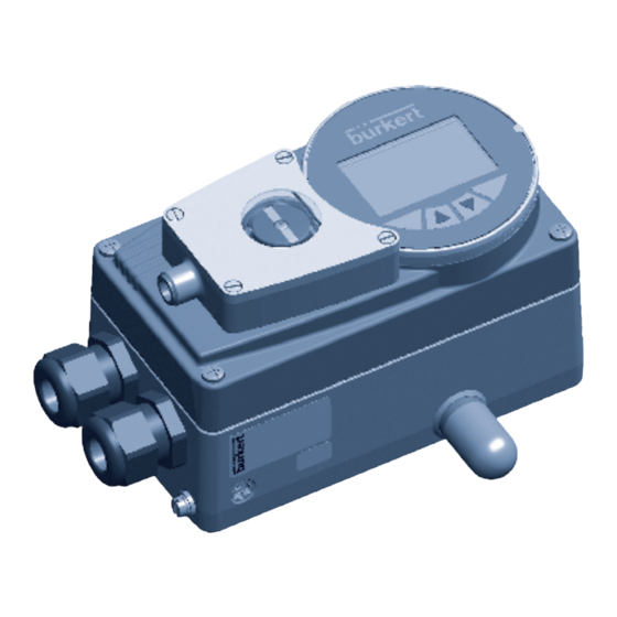
Bürkert 8792 Manuale di istruzioni per il montaggio - Pagina 4
Sfoglia online o scarica il pdf Manuale di istruzioni per il montaggio per Posizionatori di valvole Bürkert 8792. Bürkert 8792 16. Position controller and process controller with ii 3g ex ec ic iic t4 gc / ii 3d ex tc iiic t135c dc approval
Anche per Bürkert 8792: Manuale di istruzioni per il montaggio (16 pagine), Istruzioni aggiuntive (12 pagine)

Cover
for standard
display element
Fig. 2:
Connecting external position indicator
english
12
Pin Configu-
External circuit / signal level
ration
1
Supply
+10 V ... +30 V
10 ... 30 V
2
Switching
+10 V ... +30 V
output (NO)
Proximity
switch 1
3
GND
GND
4
Switching
+10 V ... +30 V
output
(NO)
Proximity
switch 2
Tab. 1:
Electrical connection
english
14
8
External position
Proximity switch 1
indicator
Housing cover
Fig. 3:
9
9.1 setting the position indicator
1 10 ... 30 V
Procedure:
→
2 Open /
10 ... 30 V
3 GND
4 Open /
10 ... 30 V
Fig. 4:
Specifying home position:
→
→
→
elecTrical connecTion
Electrical connection
sTarT-up
Loosen the 4 fastening screws and lift the cover off the
position indicator.
Fastening screws
Cover
Opening position indicator
Move the pneumatic actuator to the home position.
Rotate the complete display element until the yellow
marking bar is pointing in the required direction.
Move the first switching flag until the LED for the home
position proximity switch starts to light up.
(The LED is lit when the proximity switch is actuated).
Type 8791, 8792, 8793
Proximity switch 2
2
1
3
4
english
13
english
15
