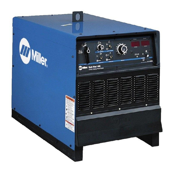
Miller 907364 Manuale d'uso - Pagina 28
Sfoglia online o scarica il pdf Manuale d'uso per Sistema di saldatura Miller 907364. Miller 907364 48. Ce and non-ce arc welding power source

4-15. Electrical Service Guide
Failure to follow these electrical service guide recommendations could create an electric shock or fire hazard. These recommenda-
tions are for a dedicated circuit sized for the rated output and duty cycle of the welding power source.
In dedicated circuit installations, the National Electrical Code (NEC) allows the receptacle or conductor rating to be less than the rating
of the circuit protection device. All components of the circuit must be physically compatible. See NEC articles 210.21, 630.11, and
630.12.
60 Hertz Models
Input Voltage (V)
Input Amperes (A) At Rated Output
Max Recommended Standard Fuse
1
Rating In Amperes
Time-Delay Fuses
Normal Operating Fuses 3
Min Input Conductor Size In AWG
Max Recommended Input Conductor
Length In Feet (Meters)
Min Grounding Conductor Size In
4
AWG
Reference: 2011 National Electrical Code (NEC) (including article 630)
1 If a circuit breaker is used in place of a fuse, choose a circuit breaker with time-current curves comparable to the recommended fuse.
2 "Time-Delay" fuses are UL class "RK5" . See UL 248.
3 "Normal Operating" (general purpose - no intentional delay) fuses are UL class "K5" (up to and including 60 amps), and UL class "H" ( 65 amps and
above).
4 Conductor data in this section specifies conductor size (excluding flexible cord or cable) between the panelboard and the equipment per NEC Table
310.15(B)(16). If a flexible cord or cable is used, minimum conductor size may increase. See NEC Table 400.5(A) for flexible cord and cable
requirements.
Failure to follow these electrical service guide recommendations could create an electric shock or fire hazard. These recommenda-
tions are for a dedicated circuit sized for the rated output and duty cycle of the welding power source.
In dedicated circuit installations, the National Electrical Code (NEC) allows the receptacle or conductor rating to be less than the rating
of the circuit protection device. All components of the circuit must be physically compatible. See NEC articles 210.21, 630.11, and
630.12.
50 Hertz Models
Input Voltage (V)
Input Amperes (A) At Rated Output
Max Recommended Standard Fuse Rating In
1
Amperes
Time-Delay Fuses
Normal Operating Fuses 3
Min Input Conductor Size In AWG
Max Recommended Input Conductor Length
In Feet (Meters)
Min Grounding Conductor Size In AWG
Reference: 2011 National Electrical Code (NEC) (including article 630)
1 If a circuit breaker is used in place of a fuse, choose a circuit breaker with time-current curves comparable to the recommended fuse.
2 "Time-Delay" fuses are UL class "RK5" . See UL 248.
3 "Normal Operating" (general purpose - no intentional delay) fuses are UL class "K5" (up to and including 60 amps), and UL class "H" ( 65 amps and
above).
4 Conductor data in this section specifies conductor size (excluding flexible cord or cable) between the panelboard and the equipment per NEC Table
310.15(B)(16). If a flexible cord or cable is used, minimum conductor size may increase. See NEC Table 400.5(A) for flexible cord and cable
requirements.
OM-222 Page 24
300 Amp Model
200
230
460
70
61
31
2
80
70
35
110
90
45
4
6
8
10
149
131
356
(45)
(40)
(108)
6
8
10
300 Amp Mode
380
400
35
33
2
40
40
60
50
4
10
10
243
269
(74)
(82)
4
10
10
450 Amp Model
575
200
230
460
25
102
89
45
30
125
110
50
35
150
125
70
12
4
4
8
342
136
180
319
(104)
(41)
(55)
(97)
12
6
6
8
l
450 Amp Model
440
380
400
31
54
51
35
60
60
50
80
80
10
8
8
326
218
241
(99)
(66)
(73)
10
8
8
650 Amp Model
575
230
460
36
124
62
45
150
70
50
175
90
10
3
8
335
144
210
(102)
(44)
(64)
(100)
10
6
8
650 Amp Model
440
380
400
440
47
75
71
50
90
80
70
125
110
100
8
6
6
292
219
242
293
(89)
(67)
(74)
(89)
8
6
6
575
50
60
70
8
328
8
65
80
6
8
