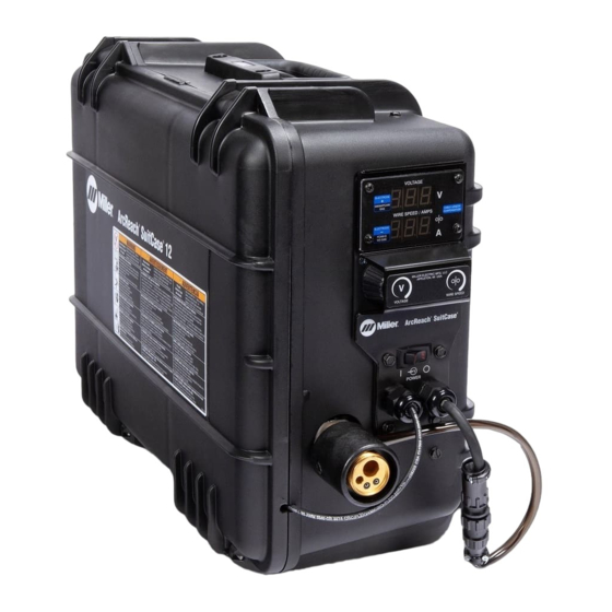
Miller ArcReach SuitCase Non-CE Manuale d'uso - Pagina 35
Sfoglia online o scarica il pdf Manuale d'uso per Sistema di saldatura Miller ArcReach SuitCase Non-CE. Miller ArcReach SuitCase Non-CE 48.

6-2.
Description Of Front Panel Controls (See Section 6-1)
1 Voltmeter
When not welding and the wire feeder is not
associated with the ArcReach compatible
welding power source or ArcReach Control,
the voltmeter will display three dashes.
If the decimal points on the voltmeter are
blinking, the wire feeder is trying to associ-
ate to an ArcReach Control or welding
power source. See Section 5-5 for details.
When the wire feeder is associated with an
ArcReach compatible welding power source
or ArcReach Control, the voltmeter will dis-
play preset voltage while idle. While weld-
ing, the feeder will display the actual weld
voltage at the wire feeder.
When connected to a non-ArcReach weld-
ing power source, the voltmeter will display
three dashes while idle. While welding, the
feeder will display the actual weld voltage at
the wire feeder.
When the wire feeder is in CC mode, the
voltmeter will display CC while idle. While
welding, the feeder will display the actual
weld voltage at the wire feeder.
Whether the wire feeder is associated or
not, the voltage displayed while welding is
an average reading over a time span of six
to eight seconds. If the weld time is less than
eight seconds, the voltage displayed may
not be accurate.
2 Wire Speed / Amperage Meter
Displays wire speed in inches per minute.
�
Complete Parts List is available at www.MillerWelds.com
Amperage displayed at the feeder is approx-
imate. Refer to power source for actual
amperage.
3 Wire Speed Control
Use control to adjust wire speed. Maximum
wire speed may be limited by arc voltage.
4 Voltage Control
Used to adjust output voltage of welding
power source when wire feeder is associ-
ated with an ArcReach compatible welding
power source or ArcReach Control. Voltage
may be adjusted while not welding.
�
If using a power source capable of
Communication while welding, the
voltage
may
welding.
Voltage control has no function when the
wire feeder is not associated with an Ar-
cReach compatible welding power source or
ArcReach Control.
5 Power Control Switch
6 Soft Start Switch
The Soft Start feature provides a smooth
start during most weld conditions. When the
trigger is pulled, the wire speed is approxi-
mately 50 percent of the weld wire speed,
as set by the wire speed control knob. After
an arc is established, the wire speed in-
creases to the weld wire speed.
When using small diameter wire, or with in-
verter power sources, it may be necessary
to turn switch off to obtain smooth starts.
7 CC/CV Switch
Use switch to match feeder with the output
of the power source.
�
The feeder will not associate with an
ArcReach Control or power source if
the switch is set to CC.
8 Trigger Hold Switch
Trigger hold allows operator to weld without
holding gun trigger. To use trigger hold func-
tion, place trigger hold switch in the ON
position.
The operator must hold the trigger for a mini-
mum of two seconds, but no longer than six
seconds before releasing it. Welding will
continue when trigger is released.
be
adjusted
while
To stop welding, press and release the
trigger.
9 Jog/Purge Switch
Pressing the Jog switch allows the operator
to jog wire without energizing the contactor
or gas valve.
Pressing the Purge switch allows the opera-
tor to purge gas lines before welding and to
preset gas flow rate at the flowmeter.
After adjusting the switches, close and latch
the door before welding.
10 Polarity Indicators
Indicate whether feeder is connected to the
welding power source Electrode Positive
(DCEP) or Electrode Negative (DCEN).
OM-278792 Page 29
