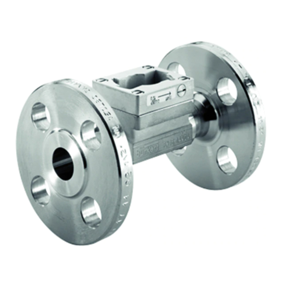
Burkert S030 Manuale di istruzioni per l'uso - Pagina 6
Sfoglia online o scarica il pdf Manuale di istruzioni per l'uso per Accessories Burkert S030. Burkert S030 11. Inline fitting

Type of connections and
Material
standard
Flanges acc. to:
EN 1092-1 / B1 / PN16
Stainless
ANSI B16-5
steel
JIS 10K
All
Brass
All
PVC
All
PP
All
PVDF
English
20
DANGER
Risk of burn injury due to high fluid temperatures.
▶ Do not touch with bare hands the parts of the product
that are in contact with the fluid.
▶ Stop the circulation of fluid and drain the pipe before
loosening the process connections.
Risk of injury due to the nature of the fluid.
▶ Respect the prevailing regulations on accident preven-
tion and safety relating to the use of dangerous fluids.
WARNING
Risk of injury due to non-conforming installation.
▶ Fluidic installation can only be carried out by qualified
and authorised personnel with the appropriate tools.
▶ Observe the installation instructions for the combined
transmitter or indicator.
Risk of injury due to an uncontrolled restart.
▶ Ensure that the restart of the installation is controlled
after any interventions on it.
English
22
K factors (pulse/litre)
DN6
DN8
DN15
440
-
106
440
278
106
440
278
116
-
-
110
440
278
118
K factors (pulse/litre)
DN15
DN20
DN20
DN25 DN32 DN40 DN50 DN65
v2
v2
1)
1)
74,5
66,5
-
49,0
74,5
66,5
-
49,0
84,7
75,3
-
52,9
89,9
74,2
-
52,9
90,3
78,0
-
57,0
See page 16
1)
7.
INSTALLATION
Safety instructions
DANGER
Risk of injury due to high pressure in the installation.
▶ Stop the circulation of fluid, cut-off the pressure
and drain the pipe before loosening the process
connections.
WARNING
Risk of injury if the fluid pressure/ temperature
dependency is not respected.
▶ Take into account the fluid pressure/ temperature
dependency according to the materials from which the
fitting is made and to the measuring device used (see
the relevant user manual).
▶ Comply with the Pressure Directive 2014/68/EU.
→
Select an appropriate fitting regarding to the flow
velocity and the flow rate of the fluid in the piping, see
the following charts:
The graph is used to determine the DN of the pipe and the
fitting appropriate to the application, according to the fluid
velocity and the flow rate.
31,8
19,8
11,4
-
31,8
19,8
11,4
-
28,5
17,3
10,2
-
28,4
17,4
10,1
-
31,7
19,0
10,9
-
English
21
21
English
23
23
