Miller XR-W Aluma-Pro Plus 15 Manuale d'uso - Pagina 12
Sfoglia online o scarica il pdf Manuale d'uso per Sistema di saldatura Miller XR-W Aluma-Pro Plus 15. Miller XR-W Aluma-Pro Plus 15 36. Air and water-cooled guns
.
Be sure that contact tip, liner, and drive rolls are correct for wire size and type. See Parts List to change parts as needed.
5-1. Equipment Connection Diagram - Single Feeder
2
3
4
5
OM-285555 Page 8
SECTION 5 − INSTALLATION
1
10
6
1
Welding Power Source
2
Contactor Control/Power Cord
3
Positive (+) Weld Cable
4
Negative (−) Weld Cable
5
Workpiece
6
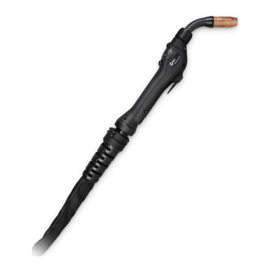
Welding Gun
7
Wire Feeder
8
Gas Hose
9
Gas Cylinder and Regulator
(Customer Supplied)
.
Shielding gas pressure not to
exceed 100 PSI (689 kPa).
10 Coolant Hoses - Water−
cooled Guns Only
9
7
8
285541-A