Burkert 8791 Manuale di istruzioni per il montaggio - Pagina 3
Sfoglia online o scarica il pdf Manuale di istruzioni per il montaggio per Posizionatori di valvole Burkert 8791. Burkert 8791 16. External position feedback option with inductive proximity
switch
Anche per Burkert 8791: Istruzioni aggiuntive (12 pagine), Manuale di istruzioni per il montaggio (16 pagine)
6.
Technical daTa.
Repeating accuracy
Temperature drift
Hysteresis
Operating voltage
Residual ripple
DC rated current
No-load current
l
0
Residual current
Rated insulation voltage
Short-circuit protection
Max. voltage drop at the switching
output compared to operating
voltage
Wire breakage safety /
reverse pole protection
Output function
Switching frequency
Protection class
english
8
7.
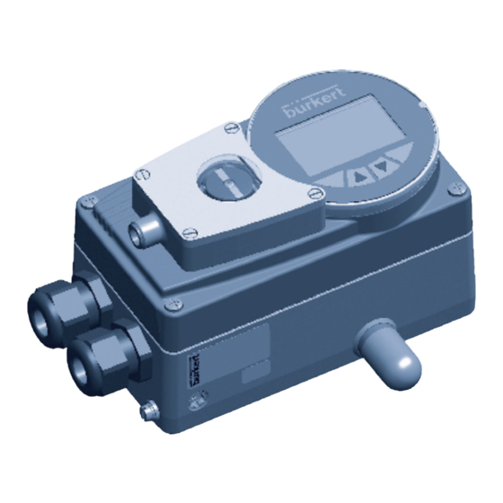
assembly
Caution!
Risk of injury from applied pressure!
Applied pressure may cause the spindle to move sud-
denly and injure fingers during installation.
•
Depressurize the device before installation.
The external position feedback is installed in two steps.
Step 1: Replace the standard display element with
the display element for the external position
feedback.
→
Loosen the 4 screws of the housing cover and open
the cover.
→
Remove the standard display element from the spindle
(see Fig. 1: ).
→
Push the display element with switching flags for the
external position feedback all the way onto the spindle
(see Fig. 1: ).
english
10
≤ 2 %
± 10 %
3 ... 15 %
10 ... 30 V DC
≤ 10 % U
ss
≤ 100 mA
≤ 15 mA
≤ 0.1 mA
≤ 0.5 kV
yes / clocking
≤ 1.8 V
yes / complete
Three-wire,
normally open
contact, PNP
≤ 0.02 kHz
IP65, IP67
6.1.
conformity with the following
standards
CE mark conforms to EMC Directive 2004/108/EC
Display element
with switching flags
for external
position feedback
Standard
display element
Fig. 1:
Replacing display element
Type 8791, 8792, 8793
english
9
Fastening
screws for
housing cover
english
11