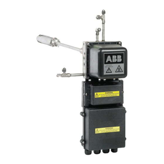
ABB Endura AZ40 Manuale - Pagina 10
Sfoglia online o scarica il pdf Manuale per Apparecchiature industriali ABB Endura AZ40. ABB Endura AZ40 16. Oxygen and carbon monoxide equivalent (coe) analyzer
Anche per ABB Endura AZ40: Istruzioni per l'uso (16 pagine), Manuale di istruzioni per l'uso (20 pagine)

8.2 CO heater block cartridge heaters (70 W)
Referring to Fig. 8.2:
1. Use a small flat-bladed screwdriver to depress the spring
connectors at terminal numbers 4, 5 and 6 and disconnect
70 W CO heater block cartridge heater wires from top
terminal block connectors A.
2. Pull CO heater block cartridge heater wires up through (left)
opening B in the flange block.
3. Carefully slide CO heater block heater insulation C
forward / up to expose the 2 x 60W cartridge heaters D
(HTR1) and E (HTR2).
CAUTION – Minor injuries
Appropriate PPE (gloves / goggles) must be worn
when performing this step. The heater block
insulation material is fragile and becomes brittle
after continuous operation. When sliding insulation
away from the manifold, handle with care.
4. Undo and remove screw F and large washer G that
retains the heaters.
5. Slide each CO heater block cartridge heater out of the CO
heater block H. If CO cartridge heaters are stuck, rotate
them or use a suitably sized rod to push them out from the
other side.
6. Slider each new CO heater block cartridge heater into the
CO heater block H.
7. Take one wire from each new CO heater block cartridge
heater and twist both wires together to form a twisted pair.
8. Apply a small amount of anti-seize compound (suitable for
temperatures up to 200 °C [392 °F]) to the thread of screw
F and secure large washer G to retain the CO heater
block cartridge heaters in CO heater block H.
9. Feed the 3 x CO heater block cartridge heater wires down
through left opening B in the flange block and make top
terminal block connections at connectors A as follows:
— connect the twisted pair to terminal 6.
— connect the free wire from cartridge heater D (HTR1)
to terminal 4.
— connect the free wire from cartridge heater E (HTR2)
to terminal 5.
10. To replace CO heater block thermocouple (T/C 1), refer to
Section 8.3, page 11. To refit sensor covers refer to
Section 7.2, page 8.
11. Refit sensor covers – refer to Section 7.2, page 8.
10
INS/ANAINST/008-EN Rev. B | Endura AZ40 | Sensor assembly | Heater and thermocouple kit
1
2
3
4
4
5
5
6
6
7
8
9 10 11 12 13 14 15 16 17 18 19
Wire color
Terminal no.
Empty
4
White / Blue
5
Blue
6
H
F
G
E
Fig. 8.2 Replacing CO heater block cartridge heaters (70 W)
A
20
Cable type
Connection
COBK HTR 1
Power
COBK HTR 2
COBK HTR 1-2
C
