Burkhard Reuter RLA4 Specifiche e manuale operativo - Pagina 7
Sfoglia online o scarica il pdf Specifiche e manuale operativo per Antenna Burkhard Reuter RLA4. Burkhard Reuter RLA4 9.
The number of steps for a 180° rotation now amounts to 232, with step 232 enabling the "Whip" mode.
Steps 0 - 231 set the loop operation from 0° to 179°. Thus, a rotational accuracy of less than 1° can be
achieved in the "less sensitive" areas around the 45° main receiving directions (planes of the loops and
45° each between the loop planes). In the "more sensitive" areas between the main reception directions,
the resolution is even better than 2°.
In order to be able to set the increased number of steps accurately, the associated control unit RSW2 has
been updated (see RSW2 description). Now, no potentiometer with a fixed rotation angle of approx. 270°
is used, but a pulse rotary encoder with an "infinite" rotation angle. For each pulse, exactly one step is
made forward or backward. This ensures that every possible step can be set accurately. Turning to the left
or to the right of "Omnidirectional" is not limited, but has no effect.
To increase the transmission reliability and expansion of control options (additional switching in antennas,
simultaneous control of multiple or combination antennas, etc.), the control unit now sends a 9-bit data
word with one parity bit. The corresponding setting of serial transmitters ("UART", "COM port", "RS-
232" ...) is now "9E2": 9 data bits, 1 parity bit with even parity, 2 stop bits. The data rate is still 125 baud.
Versions RLA4D, E and F
The versions D to F match the previous versions A to C:
- RLA4D: Normal version with 2-layer black coated loop material.
- RLA4E: "Blue version" with 4-layer blue coated loop material.
- RLA4F: Special version with loops made of flexible stainless steel.
In contrast to the older versions, the newer versions no longer have a circuit for omnidirectional reception
in "whip mode". This operating mode has proven to be barely usable with the usual installation of the
antenna (interior). Due to the omission of the circuits for this operating mode, the versions D - F now
achieve slightly better values for the IM suppression and the inherent noise in loop mode. The version of
the boards for homemade purposes is now called 4G. This board is also installed in the antenna versions
4D – 4F.
Assembly and disassembly
The RLA4 is usually shipped in partially disassembled condition. In this condition, it can be packed and
transported to save space. For mobile use, disassembly for transportation is ideal. Especially the RLA4F
can be assembled very easily and without tools. Proceed as follows:
- Unscrew the knurled nuts from the connecting bolts of the amplifier and the upper side of the threaded
rod (if unscrewed during transport, so as not to lose them).
- Two washers are provided for the bolts on the amplifier. First put one on each of the 4
connecting bolts (with threaded pin).
- Now screw the threaded rod with the large knurled nut down in the middle bolt (with internal thread).
Tighten the knurled nut slightly to lock the thread.
- At the top of the threaded rod sits a normal nut. Put a washer on top.
- Place one end of a steel strip on a connecting bolt so that it points away from the amplifier at a 45° angle.
Place the second washer for this bolt on top, screw on the knurled nut and tighten slightly.
- Bend the other side of the strip over the amplifier and secure it to the opposite pin with washer
and knurled nut. Caution! Do not bend the strip sharply, just bend it evenly! Attention! The strips are
very thin and can cause cutting when there is heavy pressure on their edges (risk of injury, danger of
damaging other things)!
- Place the middle of the strip on top of the threaded rod.
- Attach the 2nd strip just as described above. Both strips should form an angle of 90° to each other and
each 45° to the amplifier housing.
- Place the second washer on top of the threaded rod and screw on the knurled nut.
- Carefully tighten all knurled nuts hand-tight. Caution! Do not use any tools (like pliers)!
The connection bolts of the amplifier must not be twisted!
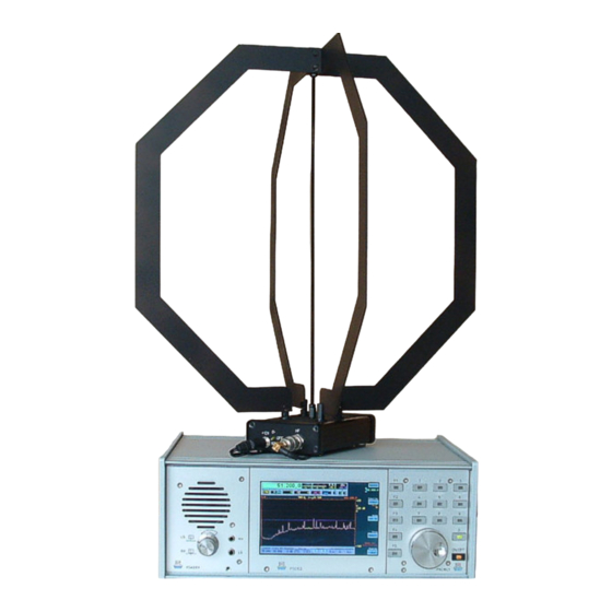
The following images illustrate the position and mounting of the individual components.
EDITION
DATE
1.5
8/19/19
K & M Burkhard Reuter
NAME
RLA4
B. Reuter
7
9
Page
of